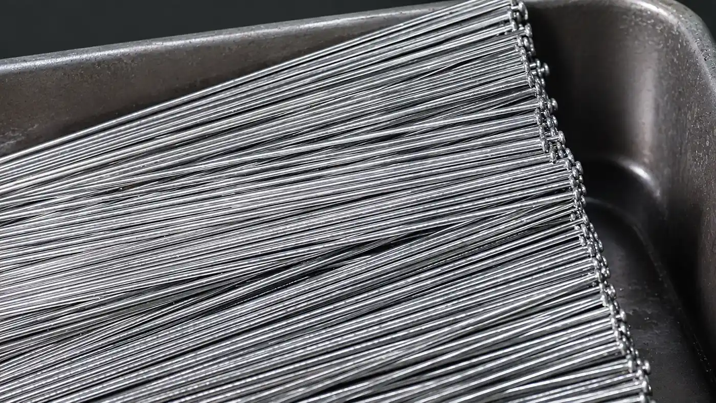
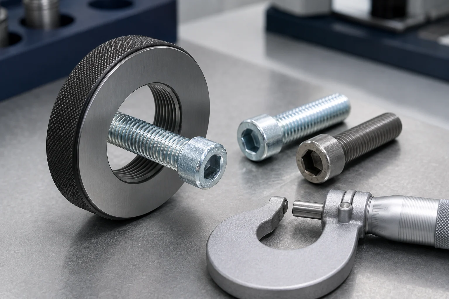
A long machine screw should enter the mating thread straight, turn freely during initial engagement, and reach its specified clamp condition without side load. If it takes extra force just to start, stop and check the joint. A powered driver can quickly turn a minor alignment or thread mismatch into a bent screw, stripped recess, or damaged tapped hole.
For machine-threaded screws entering metal parts, inserts, or nuts, follow the approved assembly drawing and work instruction. The correct torque and lubrication depend on the actual screw, finish, and joint.
Prepare the Screw and Joint
Isolate energy sources as required by the site’s maintenance procedure. Wear the required protection and support heavy or moving components before removing or installing a fastener. Have the drawing, matching bit or socket, controlled tightening tool, and any specified alignment guide available.
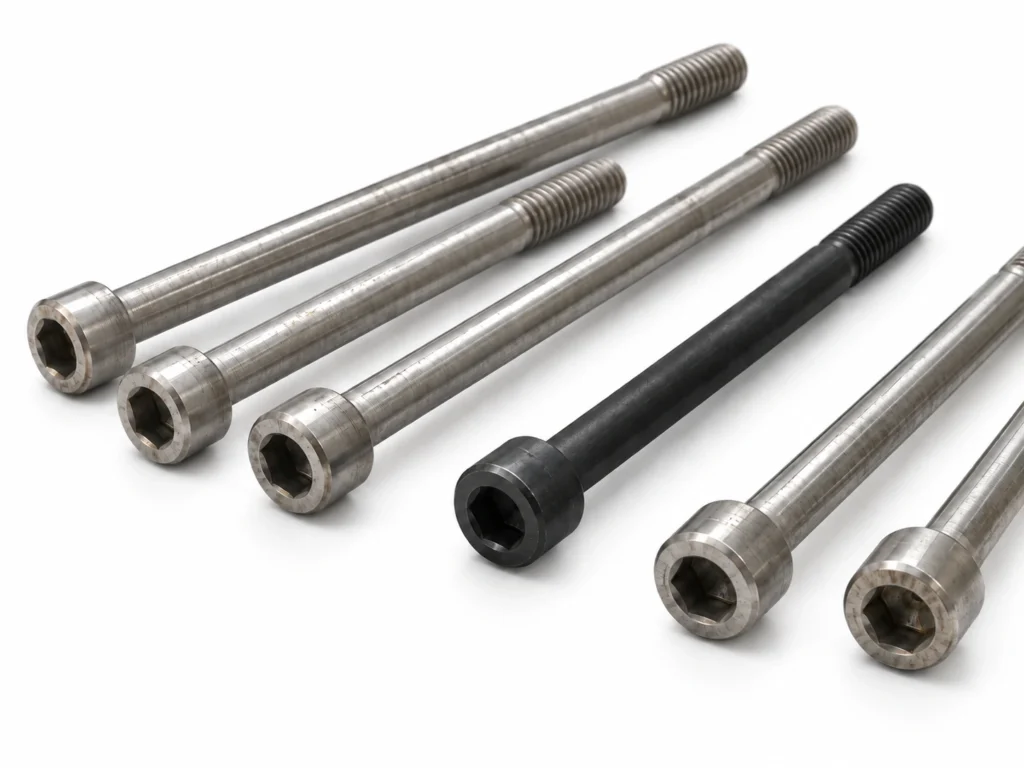
Check the screw’s diameter, pitch or TPI, length, thread zone, head, drive, material, and finish. Reject a visibly bent screw or one with damaged first threads, burrs, or coating buildup. Clean the nut or tapped hole, check the thread condition, and confirm that a blind hole has adequate depth. Bring the parts into alignment with a fixture or approved locating feature; do not use the screw to pull misaligned components sideways.
Drive the Screw in a Controlled Sequence
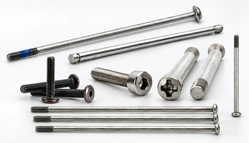
- Support the free length. Keep a slender screw from sagging or whipping while its tip approaches the mating hole. Use the assembly fixture or guide where specified.
- Start the thread by hand. Keep the screw coaxial with the hole. It should turn freely through the initial full threads. If it does not, back it out and check pitch, damage, debris, and alignment before using a powered tool.
- Keep the driver square to the head. Fully seat the correct bit or socket in the drive feature. A worn or undersized bit can strip the recess before the joint is properly tightened.
- Tighten to the approved method. Use the torque or torque-angle instruction for the actual material, coating, lubrication, and joint. A generic torque chart cannot account for every friction condition. STANLEY Engineered Fastening’s technical manual explains how friction affects the relationship between torque and preload.
- Inspect the assembled joint. Confirm head seating, specified protrusion or blind-hole clearance, screw straightness, and any inspection record required by the work instruction.
If resistance rises suddenly, the screw visibly bows, the drive starts to cam out, or the head will not seat, stop. Check for cross-threading, bottoming, a bent shank, or a mismatched thread. Stainless-on-stainless threads can gall; Bossard’s galling guidance covers surface and lubrication measures that must be considered together with the tightening method.
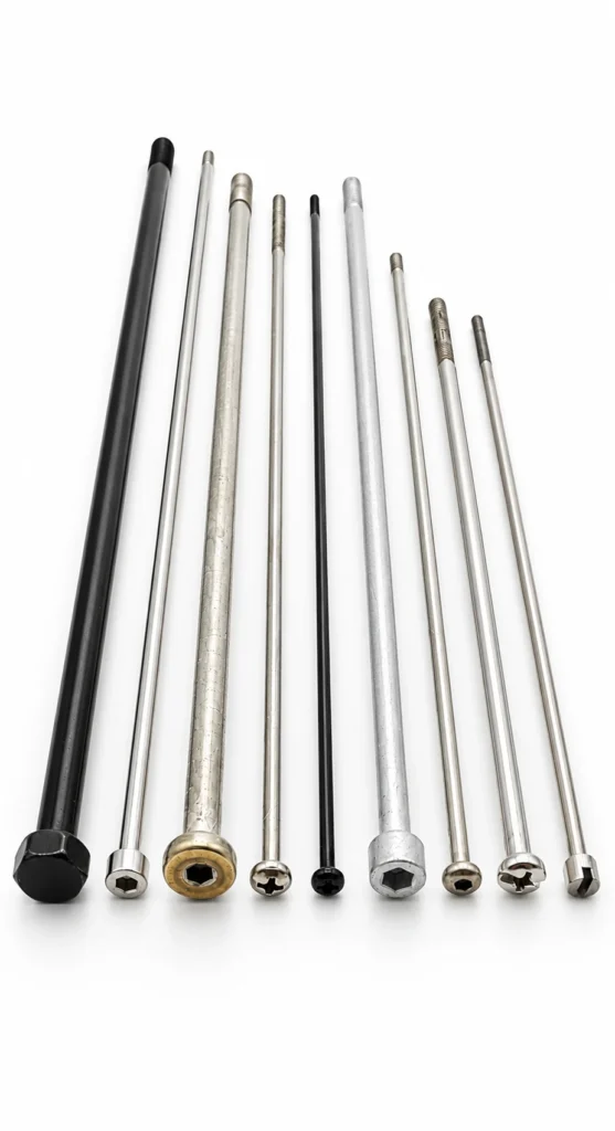
Reduce Problems in Repeat Assembly
Repeated bending or stripping usually calls for a review of alignment, screw geometry, thread fit, drive choice, coating, and packaging. Raising driver torque will not straighten an installation path. In automated assembly, also review feed support and initial driving speed; Atlas Copco’s screwdriving guide distinguishes cross-threading, damaged threads, and insufficient engagement.

At Shi Shi Tong, we can review the shank, thread zone, straightness, and drive on a custom long machine screw for your assembly. Send us the screw drawing, mating part, installation path, and observed issue to discuss a design that installs consistently.