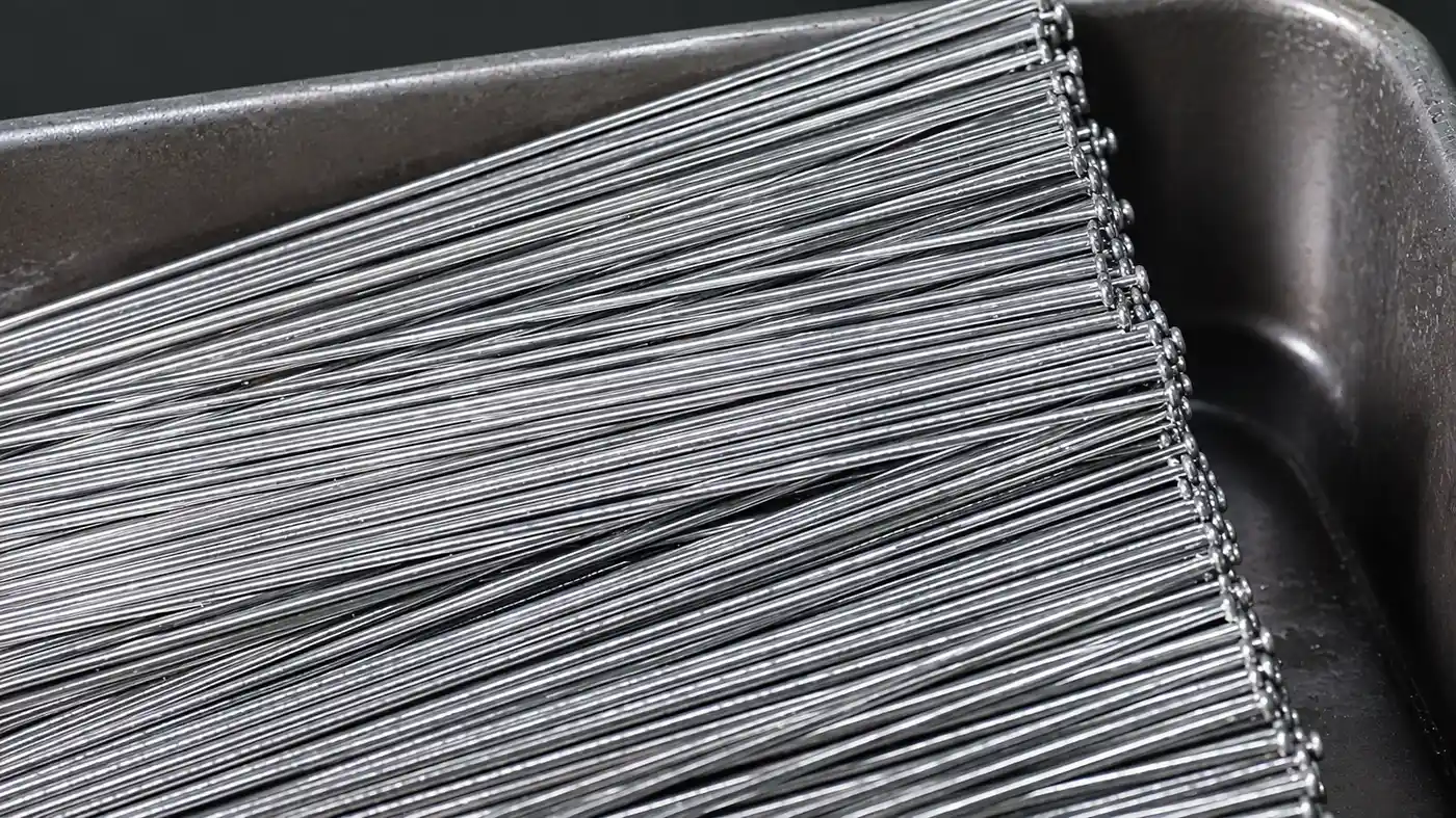
Pin-in-Six-Lobe Security Screws
A six-lobe recess with a central pin requires a driver with the corresponding profile and pin clearance. Review the drive size, recess depth and pin geometry together.
Six-lobe profile · Centre-pin clearance
A six-lobe recess with a central pin requires a driver with the corresponding profile and pin clearance. Review the drive size, recess depth and pin geometry together.
Six-lobe profile · Centre-pin clearance
A hexagonal recess with a central pin is intended for a matching pin-in-hex driver. Across-flats dimensions, engagement depth and centre clearance define the interface.
Hexagonal profile · Defined engagement
A five-lobe profile is different from a six-lobe recess or a straight-sided pentagonal socket. Identify the actual recess geometry and corresponding driver before selection.
Five-lobe profile · Specific driverOther drive configurations, including pin-in-square and pin-in-pentagon designs, are reviewed to drawing. Feasibility depends on the recess, head geometry, tooling and any applicable rights.
Drawing-based review · ToolingThese are customization paths. Dimensions and available combinations are reviewed for each drawing.
The drive is only one part of a custom security screw. Coordinate the head, seating surface, shank, thread and overall length with the mating components, installation space and intended service method.
Match the head diameter, height and underside geometry to the available space and seating surface. A countersunk head requires a corresponding seat; a projecting head needs clearance around the installed part.
Drawing-defined unthreaded sections, shoulders or steps can locate or space components where the assembly requires them. Review their diameters and lengths with the mating features.
Machine threads require a corresponding tapped hole or nut. Self-tapping designs depend on the mating material and pilot-hole conditions. Select the thread around the intended joint.
Define the overall length, threaded length and end geometry around the joint. Check engagement, screw-end protrusion and clearance in blind holes or enclosed spaces.
Material and finish are reviewed with the geometry, environment and manufacturing route. Available combinations are confirmed for the complete drawing.
A matching driver must fit the recess and clear the centre pin. It must also reach the screw through the surrounding assembly. Review the screw and driver as an interface before finalizing the design.
Match the actual recess shape and dimensions to the driver. Similar-looking security profiles are not automatically interchangeable.
Check that the driver’s centre clearance accommodates the pin without preventing engagement with the recess.
Review the recess depth and driver-end geometry so the driver can engage as intended without interference.
Check driver reach and clearance through the surrounding components, including the space needed to position and operate the tool.
If you plan to use an existing driver, include its specification for compatibility review. Driver sourcing and supply are agreed separately for each project.
An installed screw needs to seat correctly, engage the mating thread and remain accessible for the intended service work. Review the screw within the joint, including the surrounding components and the space behind the fixing point.
Check the installed head position, contact with the seating surface and clearance to adjacent parts.
Review the mating thread, engagement length and screw-end position, including blind-hole depth and the space behind panels.
Confirm that the specified tool can reach and engage the drive after the surrounding components are in place.
Consider maintenance access and the condition the screw, drive and mating thread must retain for the intended service cycle.
Review head clearance, screw-end position and access around internal components.
Coordinate the exposed head, restricted-access requirements and planned maintenance method.
Review material, finish, water exposure and mating components alongside tamper resistance.
Use the following specification fields to define the complete screw. Available dimensions, materials and manufacturing routes are reviewed against the drawing and assembly requirements.
Shi Shi Tong is a custom screw manufacturer in Shenzhen, China, with manufacturing roots dating back to 1998. The complete drawing guides process planning and inspection, with acceptance criteria agreed for the project.
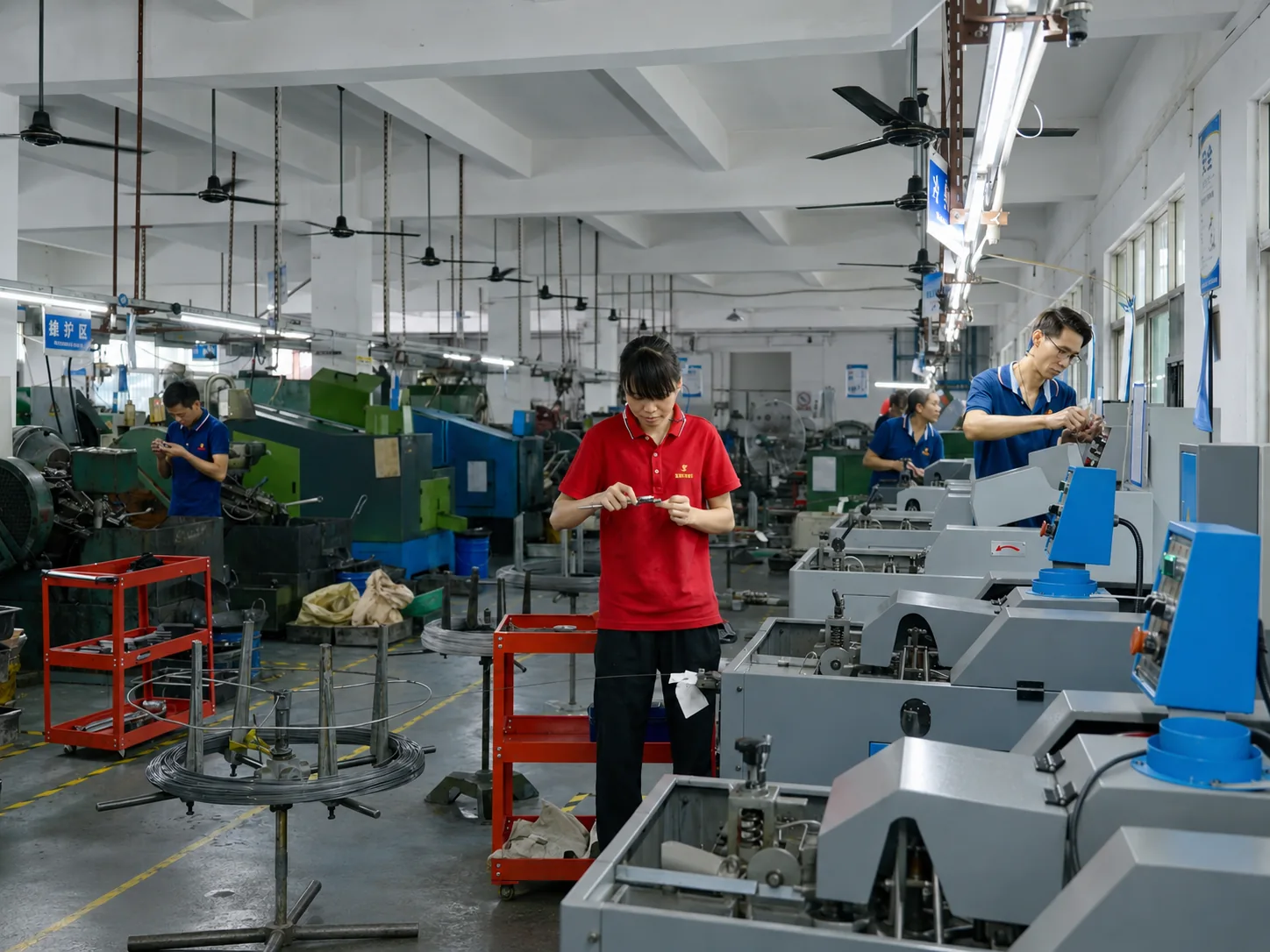
Review the recess profile, centre pin, head, seating surface and thread as connected features of the same screw. Material, structure and tolerance requirements guide the manufacturing plan.
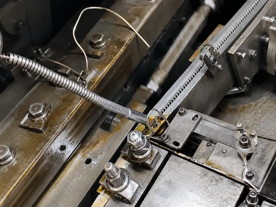
Cold heading, multi-station forming, thread rolling and secondary machining are selected around the material and geometry. Each part follows the processes its design requires.
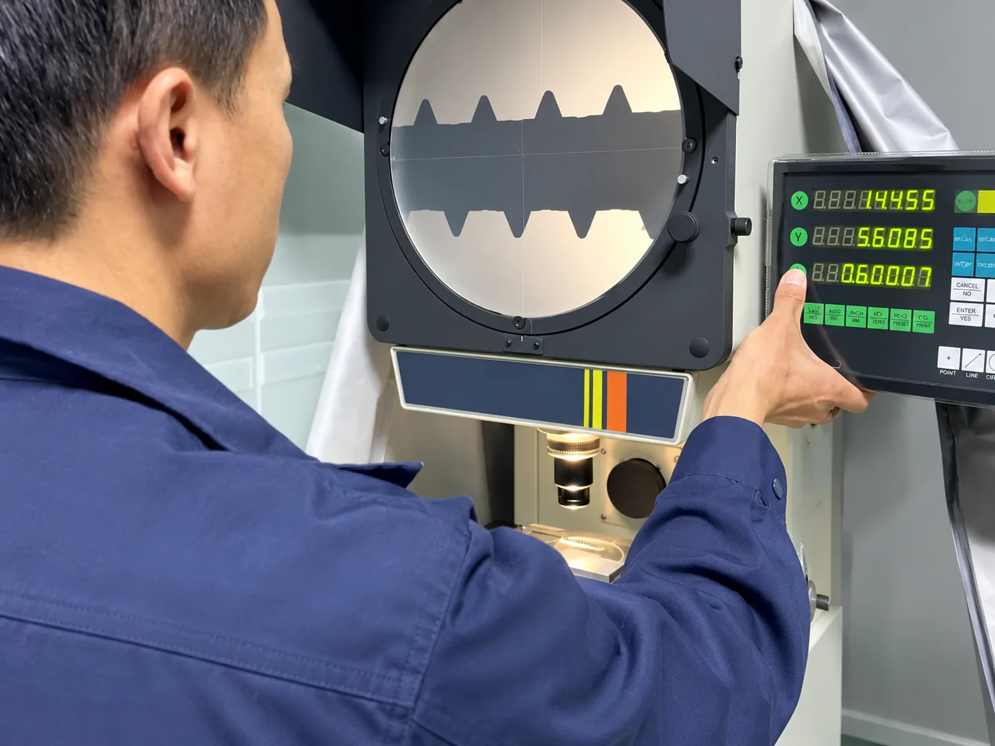
Define dimensional, thread and any project-specific functional checks for the order. Required reports, batch traceability and acceptance criteria are established for the project.
Coordinate sample evaluation with the intended mating parts and driver where relevant.
Review protection limits, maintenance needs, environmental conditions and project information before finalizing a custom security screw.
Security screws are designed to discourage removal with ordinary tools. They do not make a product impossible to open. The drive profile, availability of matching tools, exposed head geometry and surrounding enclosure all affect access.
A security drive also does not, by itself, provide resistance to vibration loosening. Tamper resistance and joint retention need to be assessed separately.
Many matched-drive designs allow planned removal with the corresponding tool, provided the drive and joint remain in suitable condition. Confirm the service method before selecting a recess or head geometry.
For repeated servicing, review access, driver engagement and the condition of the screw and mating thread over the intended service cycle. Installation and removal conditions should be agreed for the actual joint; there is no universal tightening torque for all custom security screws.
Treat tamper resistance and corrosion resistance as separate requirements. Review the material grade, finish, exposure conditions and contact with other materials. Stainless steel is not suitable for every environment without further review.
Specify the relevant acceptance conditions for the project. A coating colour does not define corrosion performance, and a laboratory test duration should not be presented as an equivalent outdoor service life.
Start with the screw drawing or sample, required quantity and intended application. Include the drive profile, head and thread geometry, material and finish requirements, plus any critical dimensions or inspection criteria.
If a driver has already been selected, include its specification. An assembly drawing or relevant photos can explain seating, clearance and service access. Manufacturing feasibility, tooling, sample requirements, minimum order quantity and delivery timing are confirmed for the individual project.
Send your screw drawing or sample details, required quantity and intended application. Include the mating-part layout and any selected driver so we can review the drive interface, custom geometry and manufacturing requirements together.