Custom Screw Tolerance Requirements
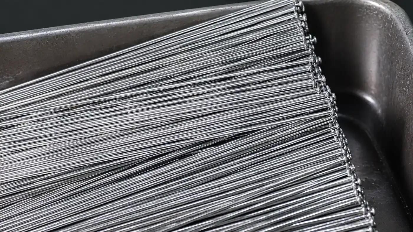
A reliable tolerance plan identifies the dimensions that control fit, movement, clamping and thread engagement. Shi Shi Tong reviews each custom screw by feature, material, manufacturing route, surface finish and inspection method before project-specific acceptance criteria are confirmed.
- Drawing and datum review
- Feature-specific tolerance evaluation
- Cold heading with selected secondary machining
- Project-specific inspection planning
Custom Screw Projects We Review
Tolerance feasibility must be assessed within the actual screw size, geometry, material and manufacturing route. The ranges below describe the main project scope; they do not mean that one tolerance applies across every dimension or product.
| Project scope | Current range or review basis |
|---|---|
| Precision custom, shoulder, micro and low-head screws | Mainly M0.8–M16, subject to geometry, material, length and tolerance review |
| Extra-long screws | Mainly M1.4–M12 |
| Extra-long screw length | Approximately 2–2000 mm, depending on structure and process |
| Custom features | Shoulders, stepped shanks, smooth sections, grooves, special ends, drive recesses, through holes and vent holes |
| Manufacturing routes | Single-die cold heading, multi-station forming, open-die forming for extra-long screws, thread rolling and selected CNC secondary machining |
| Acceptance basis | Confirmed drawing, critical characteristics, agreed inspection method and approved project requirements |
A size within these ranges still requires drawing review. Long length-to-diameter ratios, deep recesses, thin walls, large forming changes, special materials and post-treatment dimensions can change the achievable result.
A Screw Drawing Needs More Than One Tolerance
A single blanket tolerance can hide the characteristics that actually control assembly. Functional dimensions should be identified separately, referenced to suitable datums and matched with a practical measurement method.
| Screw characteristic | Why it matters | What should be defined |
|---|---|---|
| Overall and under-head length | Controls assembly stack, engagement and available clearance | Measuring convention, reference surface and cumulative dimensions |
| Head diameter and height | Affects clearance, seating and clamping position | Head profile, bearing surface, diameter, height and applicable datum |
| Drive recess | Controls tool engagement and installation consistency | Drive type, size, recess depth and inspection gauge or mating tool |
| Shoulder diameter and length | Controls location, rotation, spacing or bearing contact | Fit requirement, datum, transition geometry and functional surface |
| Shank, step and groove dimensions | Affect clearance, retention and mating-part position | Individual diameters, lengths, radii and relationships between features |
| Thread | Controls engagement and mating-part fit | Thread system, nominal diameter, pitch or TPI, tolerance class and GO/NO-GO requirement |
| Axial or cross holes | Affect venting, retention or assembly function | Hole diameter, position, burr requirement and relationship to the screw axis |
| Geometric controls | Affect rotation, alignment and assembly | Clearly defined straightness, concentricity, runout, position or angular requirement |
| Surface finish and coating allowance | Can change threads and critical diameters | Pre-treatment dimensions, coating requirement and post-treatment inspection basis |
Important: Do not use “concentricity ±2°.” Concentricity, runout, straightness and angularity describe different requirements and must use the correct datum, symbol and unit.
Prevent Tolerance Problems Before Tooling
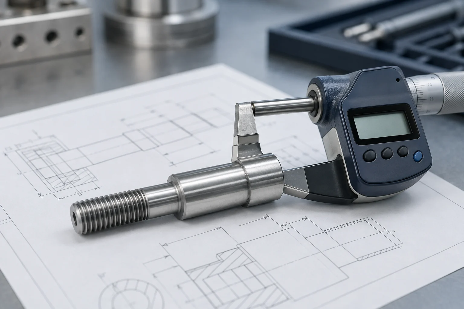
The Critical Dimension Is Not Identified
When every dimension appears equally important, production and inspection may focus on the wrong characteristics. Identify the dimensions that directly affect fit, rotation, sealing, clamping or thread engagement.
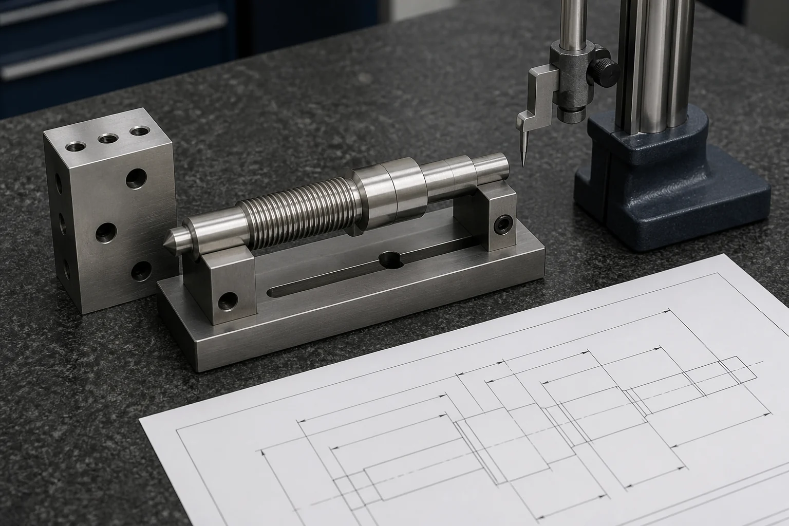
The Drawing Has No Clear Datum
The same feature can produce different results when it is measured from different reference surfaces. A defined datum gives manufacturing and inspection a consistent starting point.
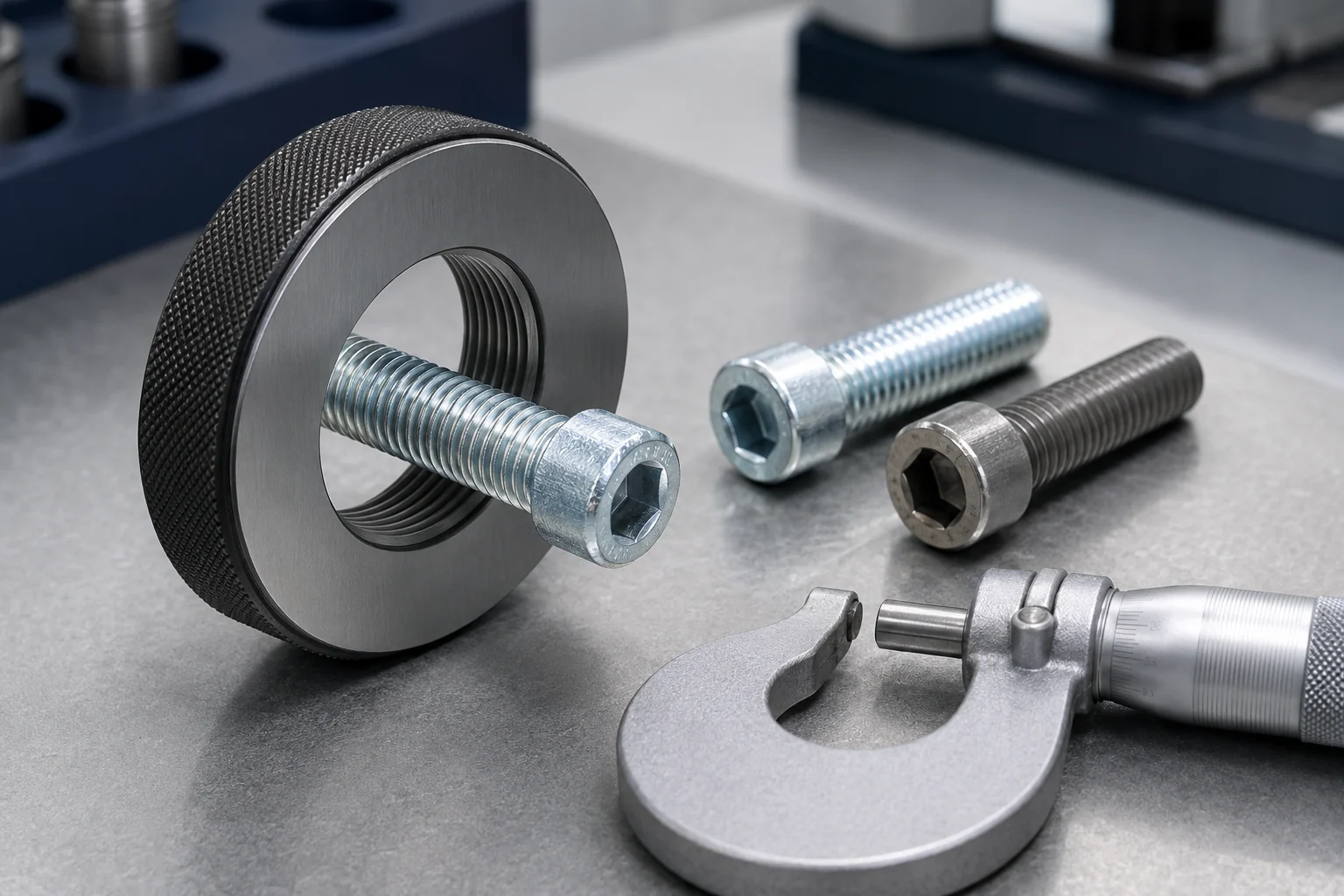
Surface Treatment Is Added After the Tolerance Is Set
Plating, coating, anodizing and other treatments can affect thread fit and critical diameters. Allowance and post-treatment acceptance should be considered before the process route is finalized.
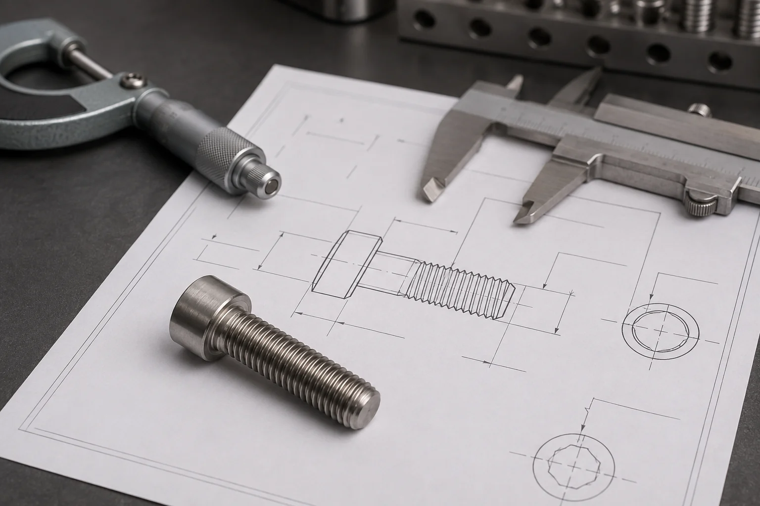
A Sample Is Approved Without a Complete Drawing
A physical sample helps with initial evaluation, but it does not define every allowable variation. A confirmed drawing records dimensions, tolerances, materials, finishes and inspection expectations for repeat production.
Match the Tolerance to the Manufacturing Route
Tolerance decisions should be made together with process planning. The suitable route depends on geometry, deformation, material, quantity and which dimensions are functionally critical.

| Manufacturing stage | Best suited to | Tolerance review focus |
|---|---|---|
| Single-Die Cold Heading | Relatively simple or near-standard formed geometry | Head formation, shank dimensions, material flow and repeatability |
| Multi-Station Forming | Larger deformation, stepped geometry, shoulders and deeper recesses | Feature transitions, forming sequence, tooling and critical formed dimensions |
| Open-Die Forming | Extra-long screws beyond conventional closed-die length capability | Length, shank geometry, deformation and project-specific inspection |
| Thread Rolling | External machine, self-tapping or drawing-specified threads | Pitch, profile, effective length, tolerance class and mating-part fit |
| CNC Secondary Machining | Local diameters, shoulders, grooves, chamfers, holes and other selected features | Critical machined dimensions, datums and the relationship to the formed blank |
| Grinding | Selected shoulder, non-standard or strict-tolerance projects | Functional diameter, surface requirement and inspection feasibility |
| Surface Treatment | Corrosion, appearance or functional finish requirements | Coating allowance, thread fit, critical diameters and post-treatment inspection |
Shi Shi Tong uses CNC as a secondary precision process where the drawing requires it. Grinding is evaluated only for selected projects. The final route is confirmed after the complete drawing, material and quantity are reviewed.
Tolerance Planning for Repeatable Custom Production
Function Before Blanket Precision
The review begins with fit, movement, clamping, thread engagement and other functional requirements, so attention can be placed on the dimensions that matter to the assembly.
Allowance for Secondary Processes
Heat treatment, surface finishing and local secondary machining are considered when they can affect threads, critical diameters or feature relationships.
Process and Inspection Reviewed Together
The manufacturing route and measurement method are considered before production criteria are finalized, reducing ambiguity between the drawing and the inspection result.
A Defined Basis for Sample and Production Review
The confirmed drawing, agreed critical characteristics and inspection requirements create a common reference for sample evaluation and repeat manufacturing.
How a Custom Screw Tolerance Plan Is Established
Define the Assembly Function
Identify the mating components, installation method, loading condition and the dimensions that control product function.
Review the Drawing and Datums
Check dimensions, tolerance symbols, reference surfaces, thread requirements and any relationship between critical features.
Select the Manufacturing Route
Evaluate cold heading, multi-station forming, thread rolling and the need for selected secondary machining.
Agree on the Inspection Method
Match each critical characteristic with an appropriate gauge, dimensional instrument, optical method or functional check.
Validate the Sample or First Article
When sampling is included in the project, compare the part with the confirmed drawing and agreed acceptance requirements.
Apply In-Process and Final Inspection
Control the agreed critical characteristics during production and verify the finished parts against the project requirements.
Quality and Inspection Built Around the Drawing
Shi Shi Tong operates under an ISO 9001 quality management system. Inspection planning is based on the product drawing, geometry, material, manufacturing route and agreed critical characteristics.
Dimensional Measurement
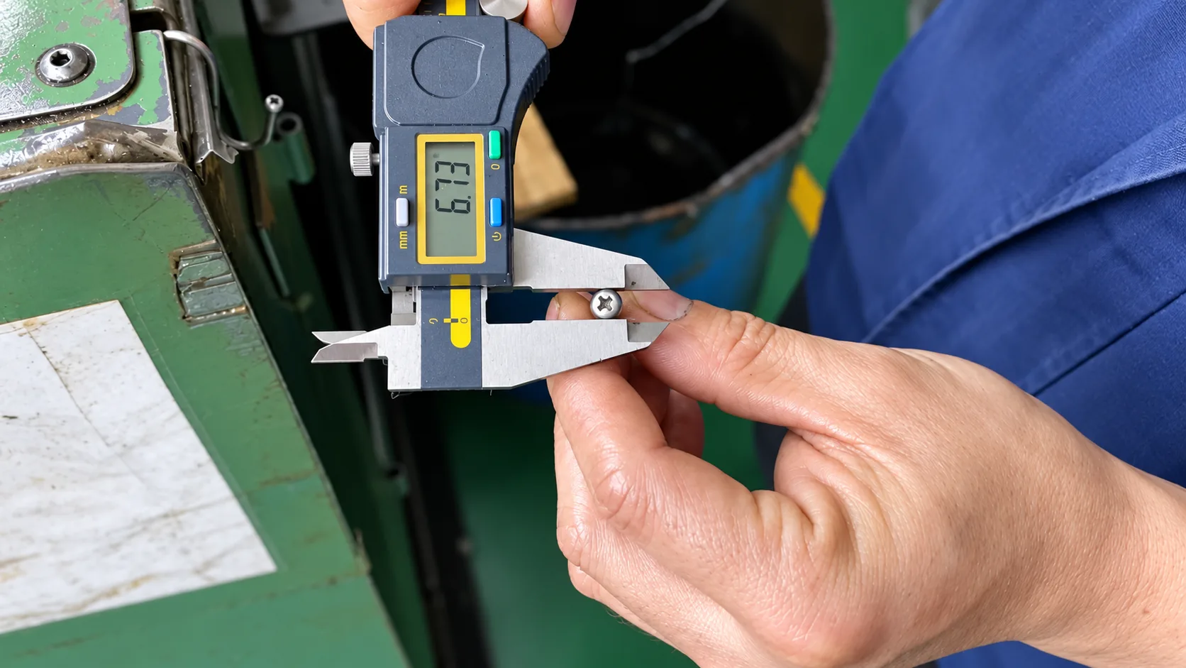
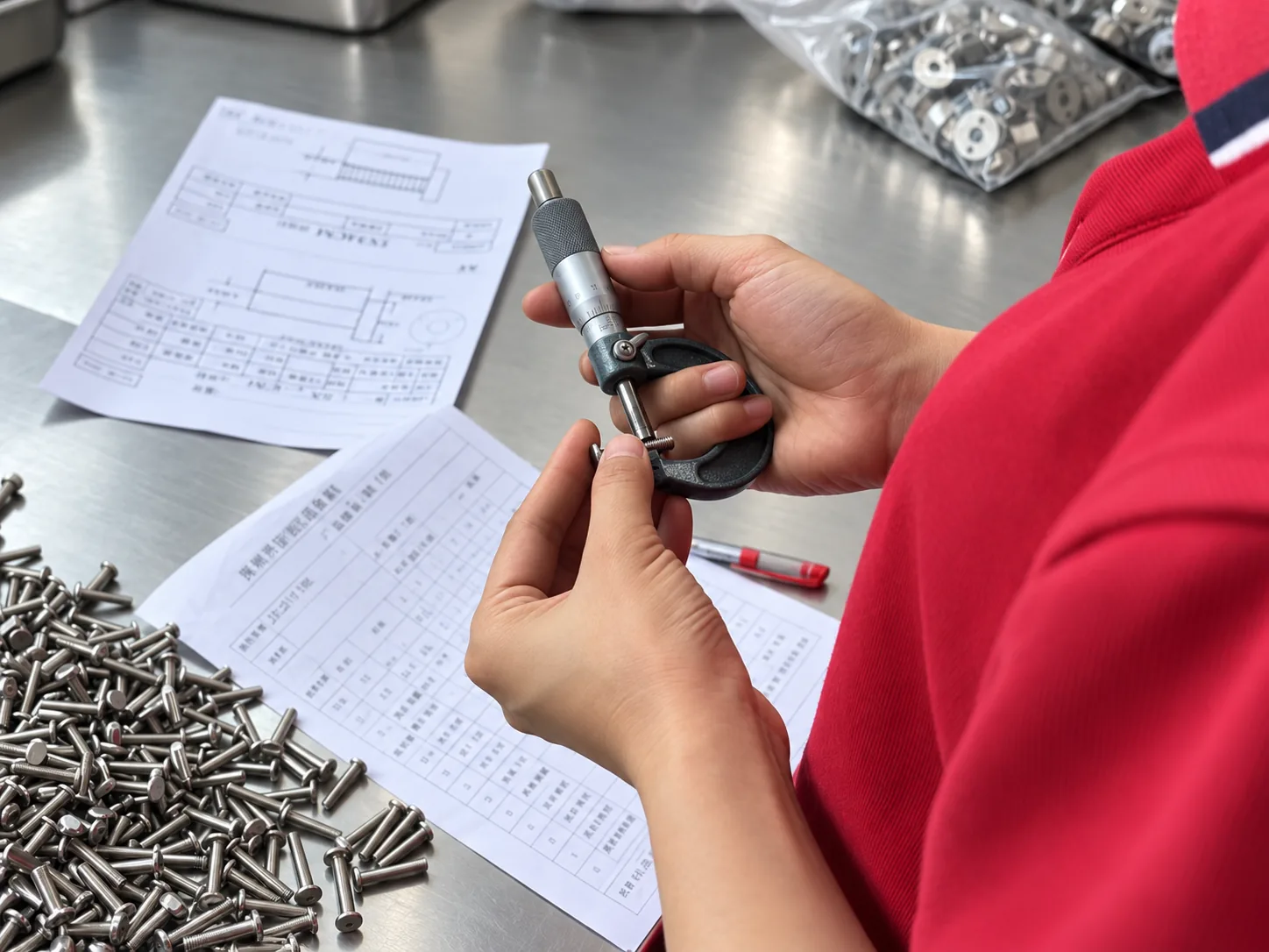
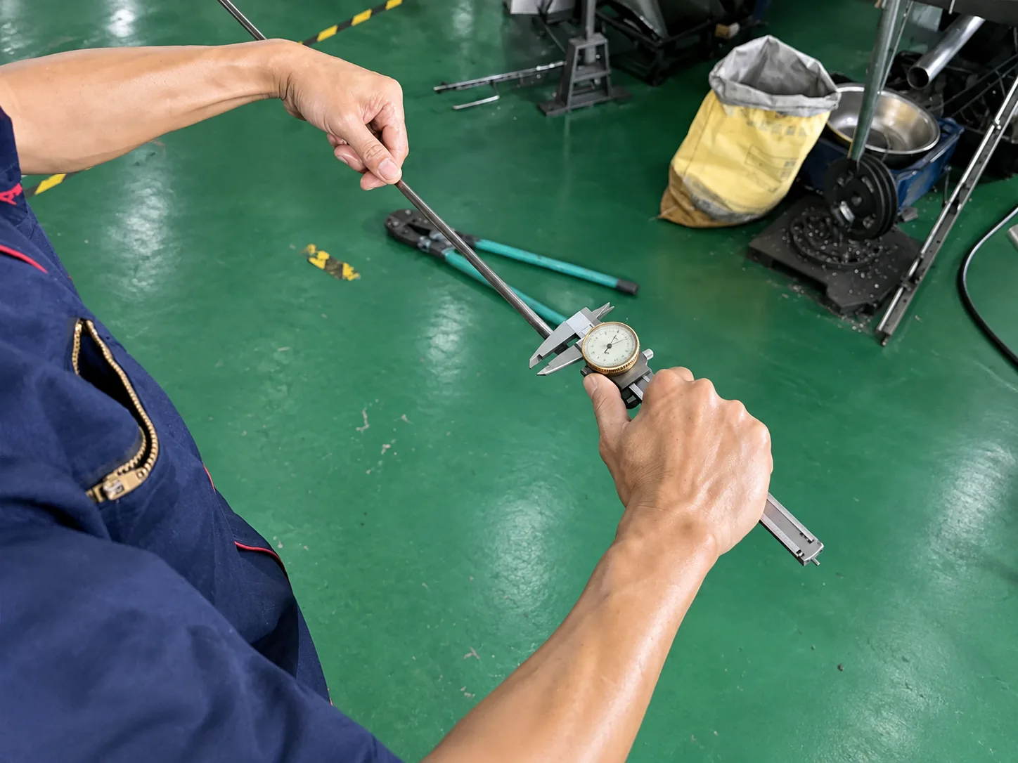
Digital calipers, outside micrometers, depth gauges, gauge blocks, pin and plug gauges, radius gauges and angle gauges are selected according to the feature and required measurement method.
Thread and Drive Inspection
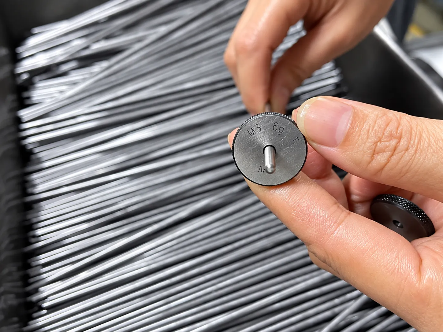
Thread plug gauges, thread ring gauges, pitch gauges and applicable recess gauges support checks of thread fit, pitch and drive geometry.
Optical and Geometric Inspection
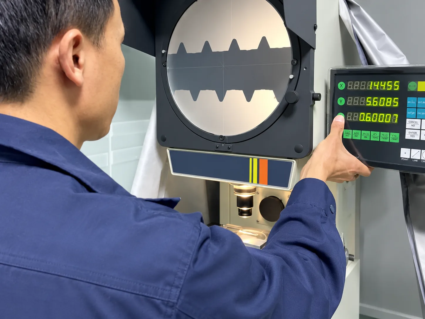
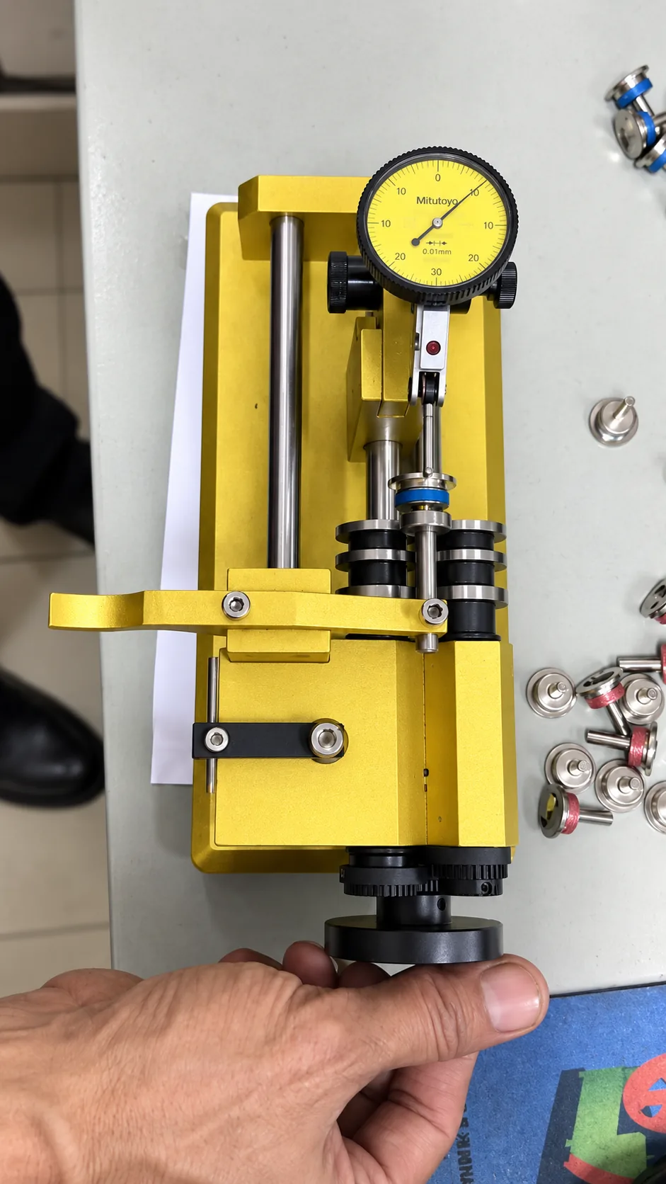
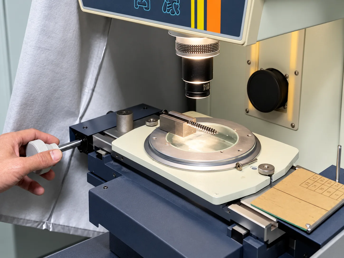
An optical projector and concentricity measuring instrument may be used when conventional contact measurement is not sufficient for the specified geometry.
Project Documentation
Depending on the agreed project scope, dimensional inspection records, material certificates and applicable test documents can be provided. Specialized testing may be arranged through qualified third-party facilities when required.
Prepare a Drawing for Tolerance Review
A useful tolerance review needs enough information to connect the screw drawing with its assembly function and production conditions.
- A dimensioned 2D drawing and available 3D model
- Overall, under-head, shoulder, shank and thread dimensions
- Clearly identified critical dimensions and datums
- Thread system, pitch or TPI, tolerance class and mating-part requirement
- Material grade, condition, hardness or heat-treatment requirement
- Surface finish, coating thickness or post-treatment dimensional requirement
- Assembly environment, mating components and installation method
- Required inspection method, sampling plan and documentation
- Sample quantity, production quantity and estimated annual demand
If the project begins with a physical sample, the sample can support measurement and feasibility review. A confirmed drawing is still recommended as the production and inspection reference.
Custom Screw Tolerance Questions
Find answers regarding feasibility, secondary machining, surface treatments, and thread specifications for your custom fasteners.
What tolerance can Shi Shi Tong hold on a custom screw?
Should every dimension use the tightest possible tolerance?
When is CNC secondary machining considered?
Does surface treatment affect screw tolerances?
How should thread tolerance be specified?
Can a custom screw be manufactured from a physical sample?

Review Your Critical Screw Dimensions
Send your drawing and identify the dimensions that control assembly, fit or function. We will review the geometry, material, manufacturing route, surface finish and inspection requirements needed to evaluate the project.
Free Technical Evaluation
28 years of custom fastener experience to ensure manufacturability and cost-efficiency.
Factory Direct Capability
48,000㎡ production base supporting M0.8 micro to 2000mm ultra-long screws.
Direct Contact
- info@fastenbydesign.com
- 13143444311
- Building 9, Tantou First Industrial Zone, Songgang Street, Bao’an District, Shenzhen, Guangdong, China