Custom Pan Head Machine Screws Manufacturer
Shi Shi Tong manufactures made-to-drawing pan head machine screws for panels, housings and equipment assemblies. Five drive styles are available for review, with head dimensions, machine threads, material and finished condition specified around the connection.
- Five drive configurations
- Custom head, length and thread details
- Drawing-based manufacturing and inspection
Pan Head Machine Screws by Drive Type
A pan head provides a raised head with a flat bearing surface beneath it. The machine thread engages a compatible nut or tapped hole. Choose the drive to suit the installation tool, then define the head and thread around the assembly.
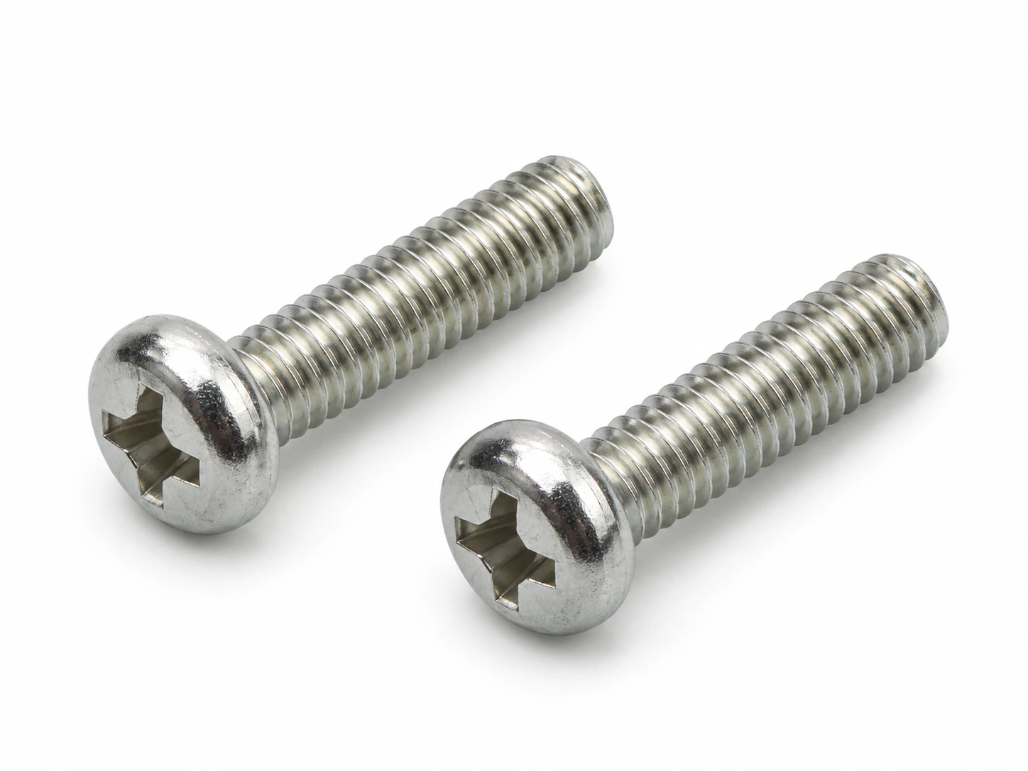
Phillips Pan Head Machine Screws
A cross-recess configuration for assemblies using Phillips tooling. Bit size and usable recess depth are selected with the head dimensions and installation requirement.
Selection focus: PH bit fit, recess depth and head clearance.

Six-Lobe Pan Head Machine Screws
A six-lobe recess for installation with a matching driver. Recess profile, depth and the surrounding head section are evaluated together for the intended tightening conditions.
Selection focus: driver profile, engagement depth and tool access.

Slotted Pan Head Machine Screws
A straight-slot configuration for assemblies that specify a flat-blade tool. Slot width and depth must suit the blade and the available access above the head.
Selection focus: blade thickness, slot width and access direction.

Pozidriv Pan Head Machine Screws
A Pozidriv cross-recess configuration with additional identification marks between the main arms. Use a matching PZ bit and specify the recess dimensions with the required head geometry.
Selection focus: PZ profile, bit size and recess fit.
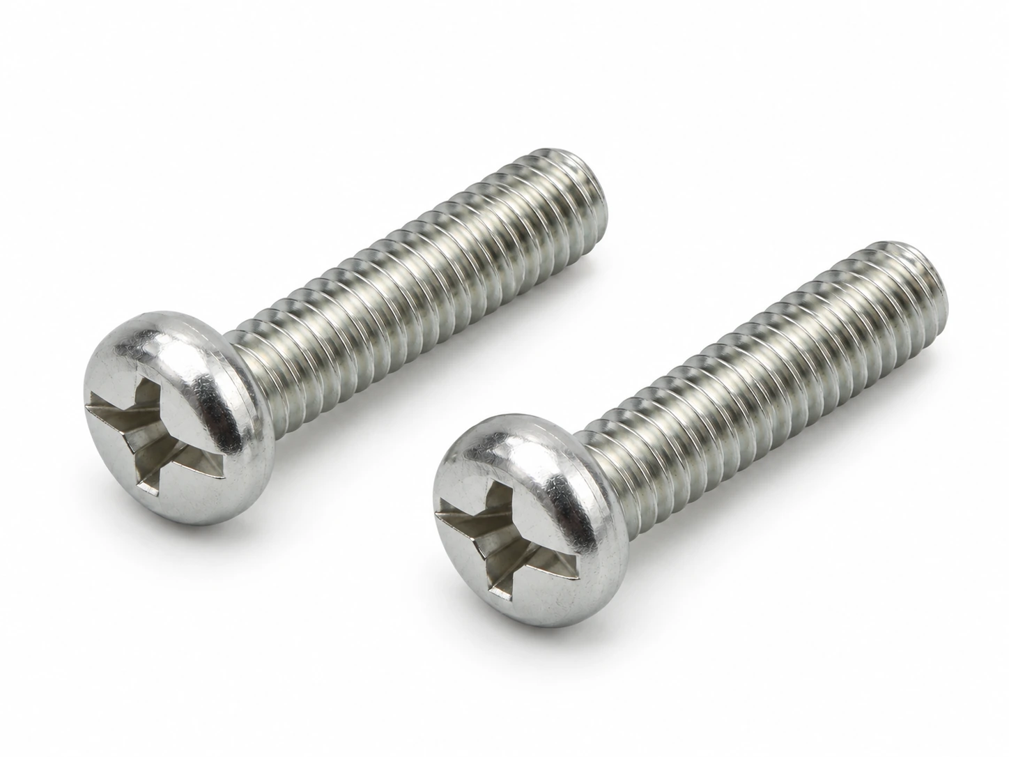
Phillips/Slotted Combination Pan Head Machine Screws
A cross recess combined with a straight slot extending across the head. The combination is specified around the intended installation and service tools, with each tool interface checked for fit.
Selection focus: cross-recess dimensions, slot dimensions and tool compatibility.
Specify the Head, Thread and Under-Head Length
The thread designation establishes the mating connection. Head diameter, head height, drive and under-head length determine how the screw fits the surrounding components.
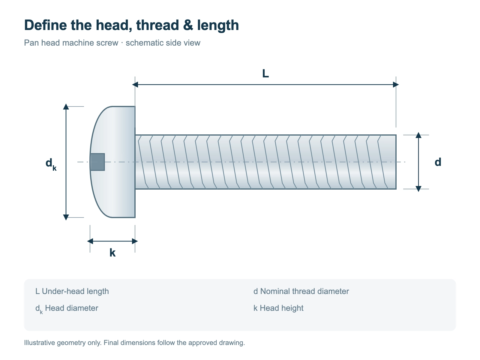
Key Dimensions to Define:
- Thread diameter
- Pitch / TPI
- Under-head length
- Head diameter
- Head height
- Recess dimensions
- Usable threaded length
| Specification | Drawing-based configuration | Selection significance |
|---|---|---|
| Thread | Metric or inch designation, pitch or threads per inch, and specified fit | Matches the nut, insert or tapped hole |
| Under-head length | Length from the bearing surface beneath the head to the end | Establishes reach through the connected components |
| Head diameter | Defined with the seating area and surrounding clearance | Determines hole coverage and the occupied footprint |
| Head height | Defined separately from screw length | Controls projection above the mounting surface |
| Drive and recess | One of the five confirmed drive configurations | Establishes the matching tool and usable engagement |
| Thread coverage | Full thread, partial thread or a specified usable threaded section | Positions complete thread where the joint needs it |
| Shank and transitions | Drawing-defined plain sections or permitted secondary features | Addresses clearance, fit and thread runout |
| Finished condition | Material, surface process, tolerances and agreed inspection | Defines acceptance after relevant processing |
Feasible dimensions are established for the complete configuration. A nominal thread size or a general manufacturing range does not define every available head, material and length combination.
Materials and Surface Requirements
Carbon steel and stainless steel configurations are reviewed with the required mechanical properties, exposure and finished fit. The material grade, drive and surface process are established for each drawing.
| Material direction | Selection consideration | Finished-part focus |
|---|---|---|
| Carbon steel | Specified mechanical requirements with a suitable surface system | Material condition, relevant treatment and dimensional allowance |
| Stainless steel | The required combination of corrosion exposure and mechanical behaviour | Exact grade and condition, thread fit and assembly requirements |
| A specified surface treatment | Appearance, exposure or functional requirements on a compatible material | Treatment system, recess fit, thread allowance and acceptance criteria |
Surface processing can change thread fit and the usable recess opening. Appearance and performance requirements should therefore be defined with the dimensions of the delivered screw.
Make the Raised Head Work with the Assembly
Match the Bearing Surface to the Component
Pan heads suit connections where the head can remain above the mounting face. On panels and covers, the bearing area must work with the hole size, component thickness and local support.
We review head diameter and the seating condition together. Where a washer is required, its dimensions and function are included in the connection specification.
Leave Room for the Head and Driver
A screw may match the thread while its head interferes with an adjacent part or prevents the tool from engaging fully. This matters in compact housings, brackets and equipment subassemblies.
Head height, head diameter and driver access are assessed as connected features. A proposed head modification is checked with the recess and remaining head section.
Keep Complete Thread in the Engagement Zone
The screw’s total reach does not establish its usable thread engagement. A short screw, a plain shank or a thread transition can change where complete threads contact the receiver.
Shi Shi Tong reviews thread start, usable length and the mating connection. Blind holes also need sufficient end clearance so that the head can seat before the tip bottoms out.

Assembly Checkpoints:
- Flat bearing surface
- Mounting component
- Tool clearance
- Usable thread engagement
- Tip clearance
Custom Features Coordinated on One Drawing
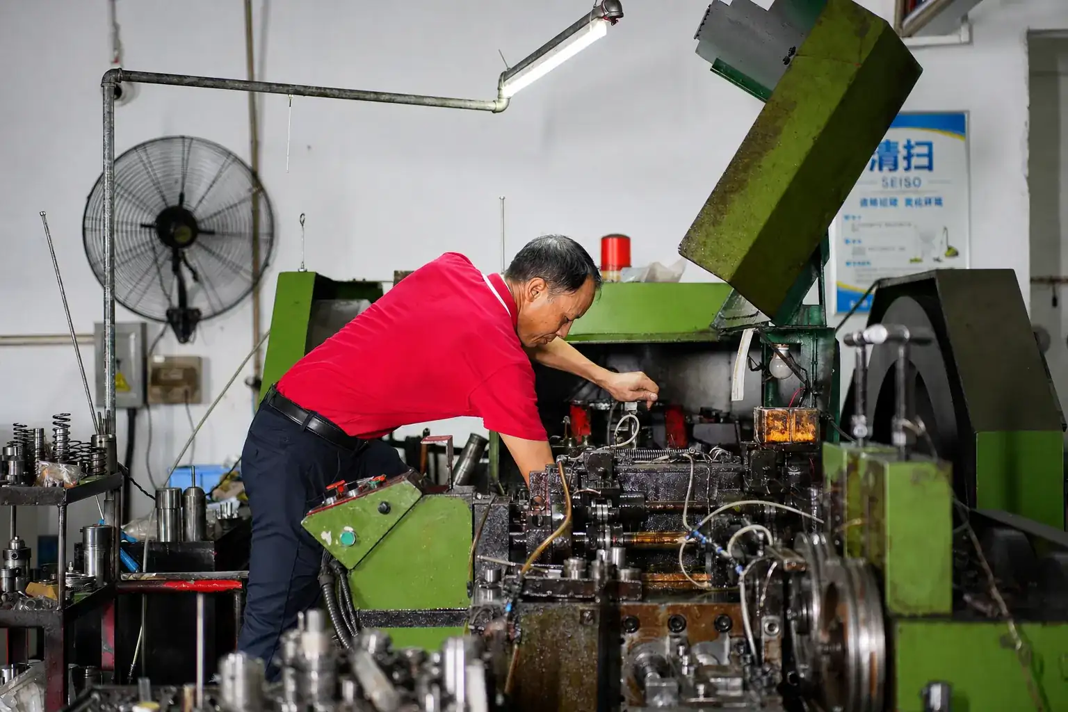
Manufacturing Process
- 1 Drawing and assembly review
- 2 Material, process and tooling assessment
- 3 Sample evaluation against agreed requirements
- 4 Production and inspection to the approved revision
Connect Head Clearance with Thread Fit
A smaller head, a different recess or a changed thread position can affect the same assembly. We review these features together and identify the dimensions that must remain fixed for the part’s function.
Plan Manufacturing Around the Finished Part
Material, head geometry, thread and quantity guide the forming and machining route. Relevant secondary operations and surface requirements are included where they affect the finished dimensions.
The approved drawing revision and agreed inspection points provide common references for sample evaluation and repeat production.
Washer Assemblies as a Separate Configuration
Preassembled washer configurations can be evaluated when the connection calls for a washer supplied with the screw. Washer type, diameter, thickness, retention and the selected head and drive are reviewed as one assembly.
Any locking or vibration requirement is assessed separately from the presence of a washer.
Manufacturing and Inspection in Shenzhen
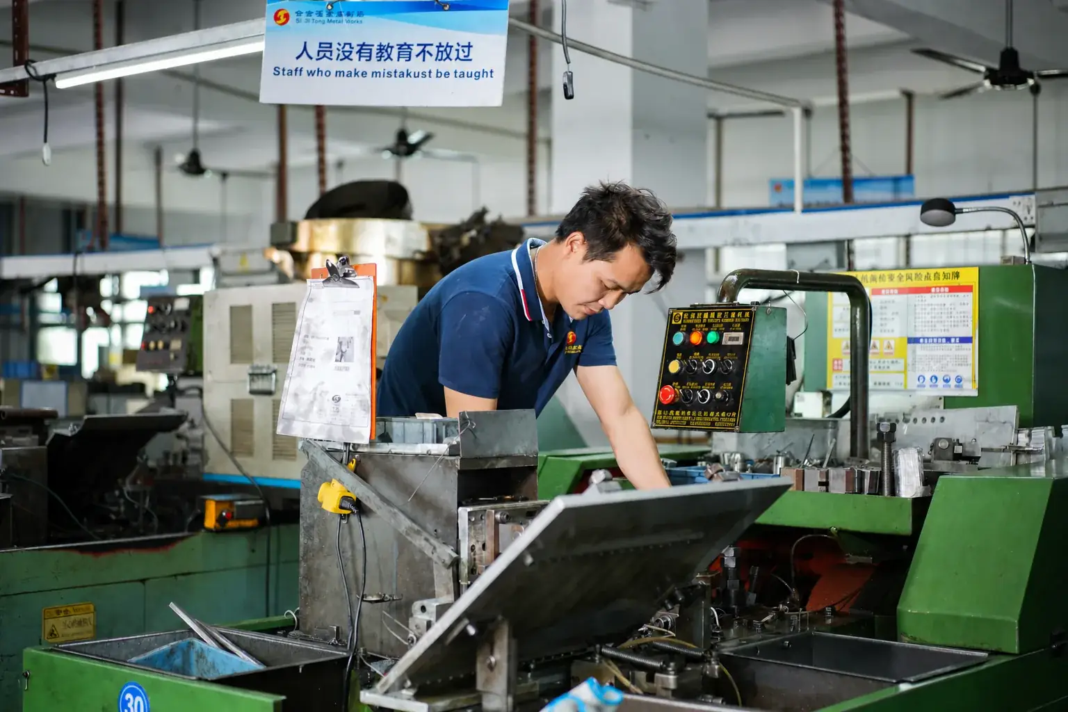
Shi Shi Tong’s screw-manufacturing history dates to 1998. Our Shenzhen operation supports custom fasteners through drawing review, process planning, sample evaluation and project-specific inspection.
For pan head machine screws, inspection connects the head profile, driver interface and thread to the approved drawing and delivered condition.
| Inspection area | What it addresses |
|---|---|
| Head | Specified diameter, height, bearing surface and profile |
| Recess | Drive dimensions, depth and matching-tool fit |
| Length and shank | Under-head measurement, usable thread and defined transitions |
| Thread | Designation, pitch, fit and applicable gauging |
| Material and surface | Agreed records and the required delivered condition |
| Additional tests | Mechanical or functional verification specified for the order |
| Documentation | Correspondence between the part, drawing revision, relevant batch and inspection results |
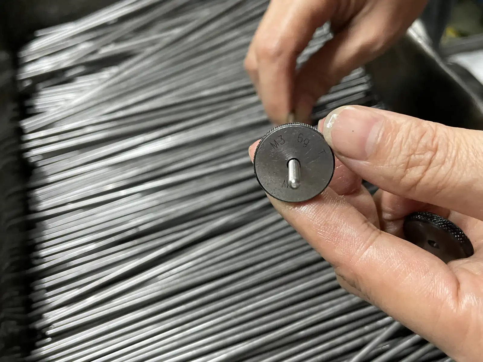
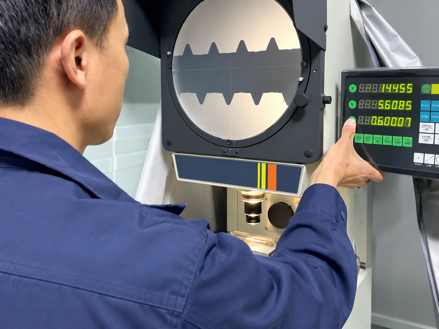
Inspection methods, sampling and additional test requirements are agreed for the project. Material documents, dimensional records and mechanical results address different parts of the acceptance requirement.
Review Quality Control and DocumentationPan Head Machine Screw Buyer Guide
Check the dimensions, head profile, installation conditions and purchase specification before selecting a custom pan head screw.
Contents
How do I measure and choose the screw dimensions?
For a conventional pan head screw, length is measured from the bearing surface beneath the head to the end of the screw. Head height is measured separately and is not included in that nominal length.
Specify the complete thread designation as well. Metric threads use diameter and pitch; inch threads use a diameter or numbered size with threads per inch. Head diameter, head height and recess dimensions complete the identification.
Choose the length around the clamped components and required thread engagement. Check complete threads, any plain shank or transition, and clearance beneath the tip in a blind hole. A short nominal length does not establish that every part of the shank is usable thread.
Shi Shi Tong evaluates the requested combination against the drawing. Required dimensions and manufacturing feasibility are confirmed for the actual head, drive and material.
How does a pan head differ from round, button and truss heads?
Compare the side profile, head diameter, head height and bearing surface. These names describe different geometries and should not be treated as automatic substitutes.
| Head form | General geometry | Selection consequence |
|---|---|---|
| Pan head | Rounded top with a short side profile and a flat bearing surface | Check head projection, hole coverage and driver access |
| Round head | A more pronounced domed crown | Compare the actual height and tool interface |
| Button head | A low rounded profile in the specified design | Confirm the bearing geometry, drive and mechanical requirement |
| Truss head | Commonly a broader, lower head form | Review the footprint, local support and surrounding clearance |
| Flat countersunk head | A conical bearing surface intended for a matching countersink | Requires a different seating condition |
A broader head can change the contact area and hole coverage, but it does not independently establish greater clamp force or remove the need for a washer.
Use the controlling drawing or product standard when dimensions matter. A low-profile requirement should be evaluated through the actual head geometry.
Which materials suit outdoor or marine exposure?
Choose the material from the exposure and mechanical requirements, rather than the head style. Rain, salt deposits, seawater contact, chemicals, temperature and contact with other metals can lead to different decisions.
316 stainless steel is often considered for chloride exposure, but it is not corrosion-proof in seawater. Pitting and crevice corrosion remain possible, especially where salts and moisture are retained. Coastal atmosphere and continuous immersion should be evaluated separately.
For coated steel, define the base material, treatment system, dimensional allowance and required acceptance test. A coating colour or laboratory salt-spray duration does not establish service life in a different environment.
For a custom order, agree the exact grade and condition with the screw geometry, installation and exposure requirements. Any testing or supporting documentation should correspond to those conditions.
How can I reduce driver slip and cam-out?
Start with the correct driver profile and size, then check engagement and the tightening process.
- Match PH bits to Phillips recesses and PZ bits to Pozidriv recesses.
- Use the specified six-lobe size or a flat blade that properly fits the slot.
- Keep the bit aligned with the screw axis and fully engaged.
- Replace worn bits and check recess condition before installation.
- Apply the tightening requirement established for the actual material, thread, finish and joint.
Pozidriv and Phillips look similar, but their intended tool profiles differ. A bit that enters the recess can still have an unsuitable fit.
Six-lobe geometry also requires correct sizing and engagement. No drive label guarantees zero slip, and increasing the torque can damage the recess, thread or connected component.
Shi Shi Tong reviews recess dimensions and tool fit with the head geometry. Installation torque and any manufacturing drive test are defined for their respective purposes.
How should I compare manufacturers and bulk quotations?
Compare quotations against the same drawing revision and acceptance requirements. The product name and nominal thread size are only part of that specification.
| Comparison area | What should be consistent |
|---|---|
| Part geometry | Head dimensions, drive, under-head length and thread coverage |
| Material and finish | Exact material requirement, condition and surface system |
| Acceptance | Dimensional checks, required tests and documentation |
| Order scope | Quantity, tooling, sample arrangements, packaging and timing |
For bulk orders, define expected demand and any repeat-order requirements. Samples, practical order quantity and delivery timing are confirmed for the particular design and manufacturing route.
Shi Shi Tong manufactures in Shenzhen, China and accepts drawing-based inquiries online. Our quotation establishes the proposed configuration, inspection scope and commercial terms for the order.
Request a Pan Head Machine Screw Review
Share your drawing or the main assembly dimensions. Include the drive, thread designation, under-head length, head dimensions, material, finish and estimated quantity where available.
Our team will review the bearing surface, tool interface, threaded connection and inspection requirements before confirming the manufacturing proposal.
Contact Information
Phone / WhatsApp
Discuss Your Drawing on WhatsApp