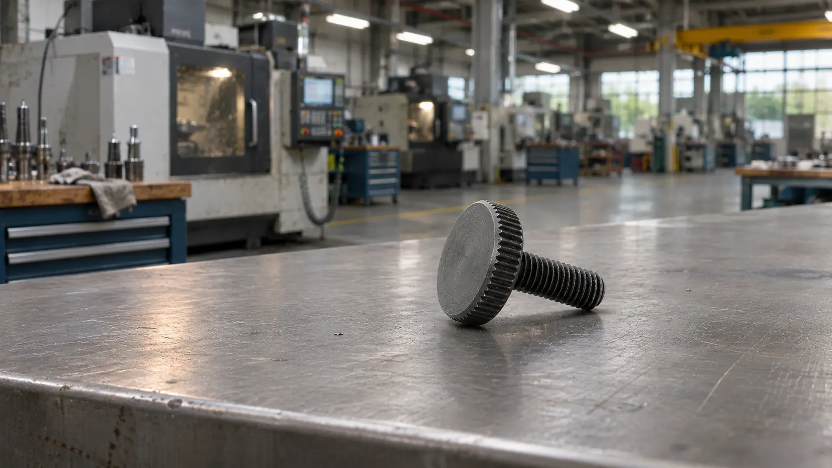
Flat knurled thumb screw with a diamond-knurled rim

Knurled Thumb Screws from a Custom Manufacturer

Hand-operated fastening starts with a head you can reach and a thread that fits. Shi Shi Tong develops drawing-based metal thumb screws in flat, raised-head and cylindrical configurations, with grip geometry, seating features and thread dimensions reviewed together.

Made to drawing in Shenzhen, China.

Compare Head Configurations

Three Knurled Head Configurations

A knurled thumb screw combines an external machine thread with a textured head intended for finger operation. Head diameter, height and access space determine how that grip can be used within the assembly.

Choose the head profile first, then define the grip texture, seating features, thread and material for the drawing. These configurations are starting points for custom manufacture.

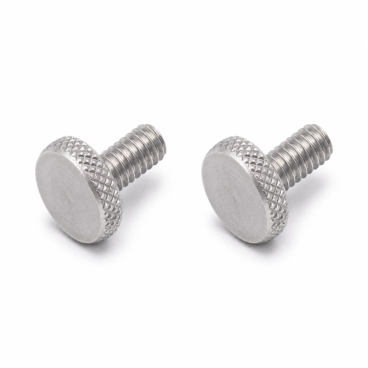
Flat knurled thumb screw with a diamond-knurled rim

Flat Knurled Thumb Screws

A shallow disk head with a knurled rim. It can suit assemblies with limited space above the head, provided enough of the rim remains accessible for the fingers. The flat profile describes the head form; it is not a countersunk seat.

Compare installed head height and accessible rim diameter.

Slotted raised-head knurled thumb screws with an under-head boss

Raised-Head Knurled Thumb Screws

A broad grip head supported above an underside boss or neck. This separates the grip from the seating region and creates a different finger-access envelope. The illustrated configuration also includes a slot for a specified tool-assisted operation.

Compare grip elevation and clearance around the head and boss.

Cylindrical knurled thumb screw with a diamond-pattern grip

Cylindrical Knurled Thumb Screws

An elongated cylindrical grip with a knurled side surface. The grip extends along the screw axis, offering a different contact length from a thin disk. Its diameter and projection need to fit both the surrounding components and the operator’s access path.

Compare grip length and the available radial and axial space.

Choose the Grip for the Space Around It

A knurled surface helps only when it can be reached. A compact head may fit the closed assembly yet leave too little room to turn it during service. Compare the complete finger envelope as well as the installed head dimensions.

Assembly priority Head configuration to compare Selection trade-off
Limited space above a cover or panel Flat knurled head Less axial projection, but a shallow rim leaves less edge height to grip. Check side access.
A grip that needs separation from the seating surface Raised head with an underside boss or neck The elevated grip changes access, while the boss and head need their own clearances.
A longer side surface for finger contact Cylindrical knurled head More grip length along the axis, with additional projection that must clear adjacent parts.
Compact electronics or instrument covers The profile that fits the actual cover and service position A small thread does not establish a usable head size. Compare head diameter, finger access and the permitted tightening method.

Straight and diamond knurl patterns

Straight knurl presents parallel ridges; diamond knurl uses intersecting ridges. Specify the required pattern, finished outside diameter and edge condition, then evaluate it with the actual access and operating conditions. Select the pattern with the actual access, edge condition and required operating method in mind.

Thumb screw configurations with straight and diamond knurl patterns

Straight and diamond knurl patterns on metal thumb-screw configurations.

Make the Head Seat Before the Stem Bottoms

A thumb screw can turn smoothly yet stop before its intended bearing surface seats. The cause may be a thread runout, an interfering neck or shoulder, or a stem that reaches the bottom of a blind hole. We review those features together with the mating thread and the actual seating plane.

Diagram illustrating thumb screw features

Key Features

  • Grip diameter
  • Grip height
  • Seating plane
  • Neck or shoulder
  • Usable thread
  • Thread runout
  • Mating thread
Feature What it controls Drawing and fit check
Head diameter and grip height Finger access and the installed envelope Define both dimensions with the surrounding clearance.
Boss, neck or shoulder Location of the seating region and passage through the mating part Check its diameter and length against the hole, counterbore or clearance section.
Thread designation Compatibility with the nut or tapped feature Retain the complete metric or inch designation, pitch or TPI, and fit requirement where specified.
Usable threaded length and runout The portion available for engagement Locate incomplete threads and any relief; do not treat the whole visible threaded region as full engagement.
Length from the defined seating plane Stack accommodation and blind-hole clearance State the drawing datum and verify that the stem does not bottom before seating.
Bearing face or collar Where the part contacts the assembly Match the intended contact surface and its clearance to the mating geometry.
Finished condition Final thread, grip and seating fit Include the relevant finish allowance and inspect in the specified condition.

Raised heads and shoulders can make a catalogue length ambiguous. The drawing should identify the seating plane and the dimensions taken from it.

Review tolerance requirements

Custom Features Planned as One Part

Seating, shoulder and drive features can be considered alongside the selected grip profile. Their dimensions and combinations are reviewed for the actual part rather than assumed to fit every head style.

Knurled thumb screw with a collar beneath the grip head
Knurled head with a defined collar beneath the grip.
Straight-knurled thumb screws with a smooth shoulder and threaded end
Smooth shoulder and threaded-end configuration.
Configuration feature Purpose in the drawing What remains to be defined
Collar beneath the grip Establish a defined contact region below the head. Collar diameter, thickness, seating face and clearance.
Smooth shoulder or stepped shank Introduce a defined plain section before the threaded end. Shoulder diameter and length, mating-hole fit and the start of usable thread.
Slotted tool-assisted head Provide a specified drive in addition to the knurled grip. Slot geometry, permitted tool and tightening requirement.

Grip and connection reviewed on the same drawing

Shi Shi Tong reviews head proportions, knurl geometry, seating features and the threaded stem together. This connects the hand-access requirement with the part’s manufacturability and mating fit before tooling and sample requirements are established.

A manufacturing route for the defined metal part

Material, geometry, quantity and acceptance requirements guide the choice of forming, turning and any required secondary machining. Tooling and sample validation are planned for the selected route; one process sequence is not assumed for every thumb-screw design.

If the screw must remain attached to a panel after disengaging from its mating thread, the retaining interface needs a separate captive-screw design.

Explore captive screw configurations

Manufacturing and Inspection in Shenzhen

Shi Shi Tong has been manufacturing screws since 1998. Drawing review, process planning and sample validation connect the specified grip and thread geometry with the production requirements for the part.

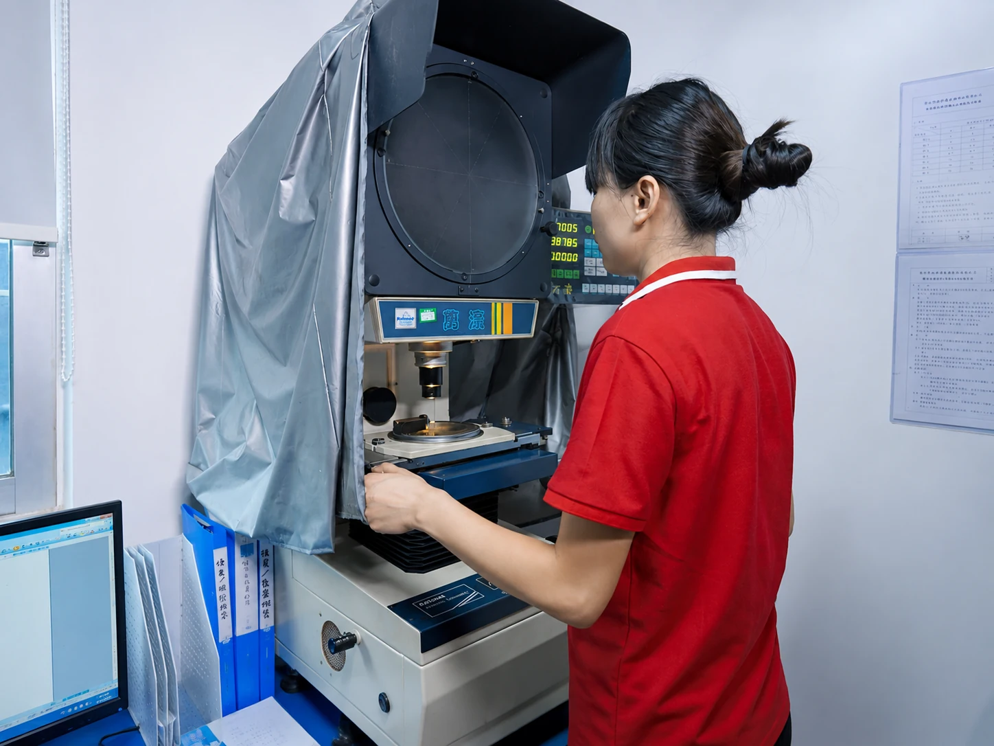
Inspection planning can include head and knurl dimensions, edge condition, shoulder or collar dimensions, thread gauging and the finished seating condition. Optical profile inspection and other checks are selected against the approved drawing and acceptance requirements.

Where the assembly requires a defined tightening performance, the test conditions and acceptance criteria are agreed for the relevant configuration.

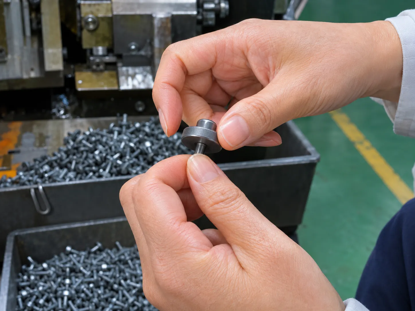
Shi Shi Tong operator working beside screw manufacturing equipment
Screw manufacturing at Shi Shi Tong.
Optical profile inspection of a screw thread
Optical profile inspection of screw geometry.
Thread gauge inspection of a metal fastener
Thread gauge inspection of a metal fastener.

Knurled Thumb Screw Selection Guide

Use these checks to identify an existing thread, compare materials and define the operating and purchasing requirements.

How do I identify the thread on an existing thumb screw?

Measure the outside diameter across the thread crests, then identify the pitch with an appropriate thread-pitch gauge. Metric pitch is stated in millimetres; Unified inch threads use threads per inch. The complete designation needs both the diameter and pitch or TPI.

Use the mating nut, tapped hole or original drawing to verify the proposed identification. Similar-looking threads are not interchangeable, and forcing an uncertain match can damage the connection. The knurled head diameter is a grip dimension, not the nominal thread size.

For a replacement or drawing-based part, retain the seating datum, usable thread length, neck or shoulder details and any specified thread fit. Shi Shi Tong reviews these together with the selected flat, raised-head or cylindrical grip.

Key Measurements

Thread outside diameter • Pitch

Stainless steel or brass: which should I specify?

Choose from the service conditions and the required properties of the finished part. Stainless steel is a common starting point where corrosion resistance is a priority. Brass is often considered for machined components, specified contact requirements or a brass appearance. Neither material name alone establishes durability in every assembly.

Selection point Stainless steel Brass
Grade and condition Specify the exact grade, such as 304 or 316L where appropriate, and the required condition. Specify the exact brass alloy and condition rather than accepting any yellow metal.
Service exposure Match the grade to moisture, chemicals, temperature and mating metals. Check the alloy’s compatibility with the exposure and adjacent materials.
Repeated operation Review the mating thread, contact surfaces and wear or galling conditions for the actual pair. Review thread and shoulder properties, contact wear and finish requirements for the actual alloy and mating pair.
Finish and fit Include the specified surface condition and its effect on grip and thread fit. Define whether the brass appearance or another finish is required, including allowance at threads and seating faces.

For Shi Shi Tong’s custom thumb screws, the material is reviewed with head proportions, knurl detail, thread and manufacturing route. A material direction does not establish that every grade and head combination is available as a standard part.

When should I use a slot or other tool-assisted drive?

A tool-assisted drive can be considered when the assembly specifies tool access or a controlled tightening method in addition to finger operation. The slotted raised-head configuration provides an example; the drive geometry and permitted operating method still need to be defined for the part.

A slot does not authorize unlimited additional tightening force. The head, recess, threaded stem and mating feature must be suitable for the specified tool and tightening requirement. Hand tightening also varies with access, grip conditions and the operator, so it should not be treated as a guaranteed torque or clamping force.

If a different recess is required, review it as a separate geometry and manufacturing requirement rather than assuming it can be added to every thin or cylindrical head.

What should a bulk-order quotation define?

Use one agreed drawing revision and finished-part specification when comparing quotations. Head shape, knurl detail and the seating arrangement can change the requirement even when two screws have the same nominal thread.

Compare the defined scope:

  • Head profile, grip dimensions, knurl pattern and any drive recess.
  • Collar, neck or shoulder dimensions, seating datum and usable thread.
  • Complete thread designation, material grade, condition and finish.
  • Sample and tooling arrangements, order quantity and repeat-order basis.
  • Inspection, documentation, packaging and delivery terms included in the quotation.

Shi Shi Tong reviews the configuration before establishing the manufacturing route and quotation. Sample quantities, production minimums, tooling charges and lead time are confirmed for the individual project.

Discuss Your Knurled Thumb Screw Drawing

Share the head configuration, grip dimensions, thread designation, material, finish and estimated quantity. Include the seating details and available finger or tool space so we can review the complete configuration.

A drawing or sample reference helps define the manufacturing, sample and inspection requirements for your project.

or drag and drop

Attach a drawing or specification if available.