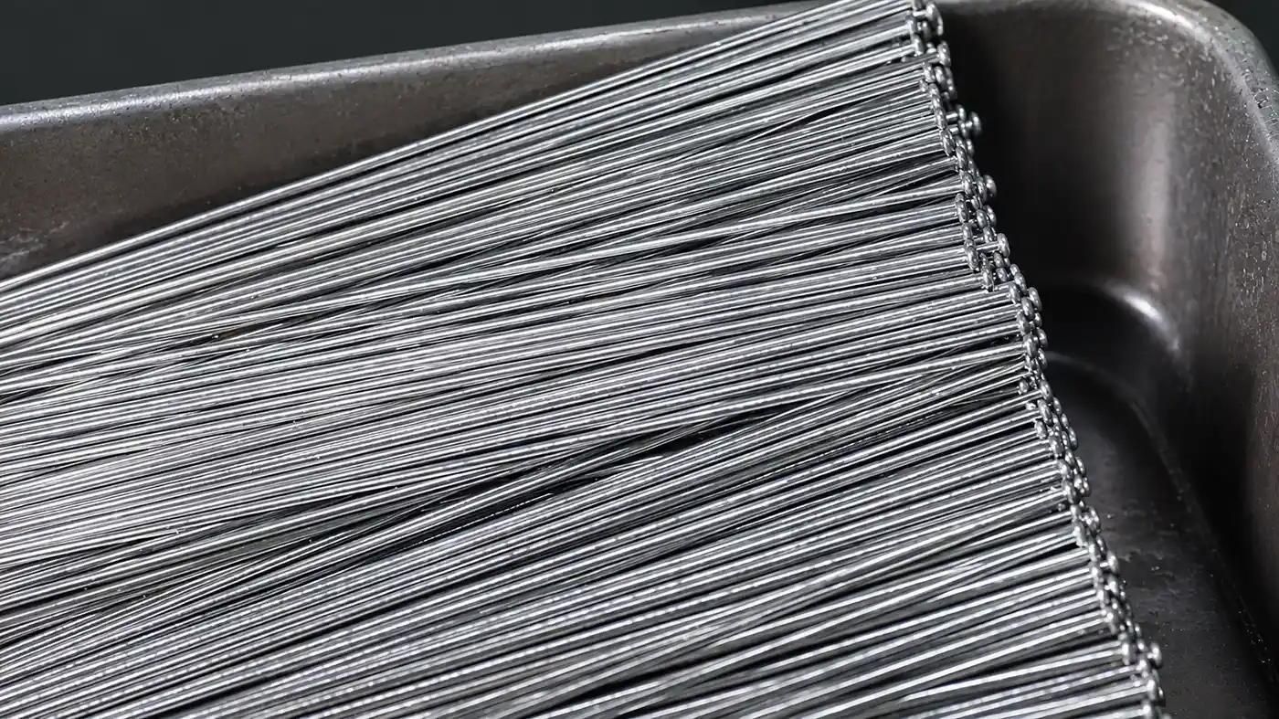
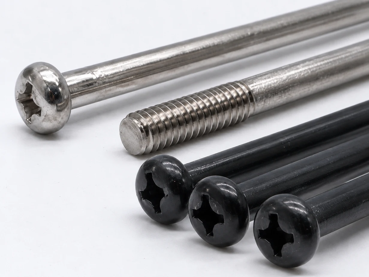
Manufacturer of Custom Long Phillips Screws for Metal Assemblies
Shi Shi Tong manufactures long Phillips machine screws around the approved drawing, including custom head profiles, recesses, overall lengths, thread zones, materials and surface finishes. Projects within M1.4–M12 and lengths from 2–2000 mm can be evaluated according to the complete geometry and production route.
Final feasibility depends on the diameter-to-length ratio, head volume, recess, thread, material, tolerance, finish and required production quantity.
Long Phillips Screws for Drawing-Specific Assemblies
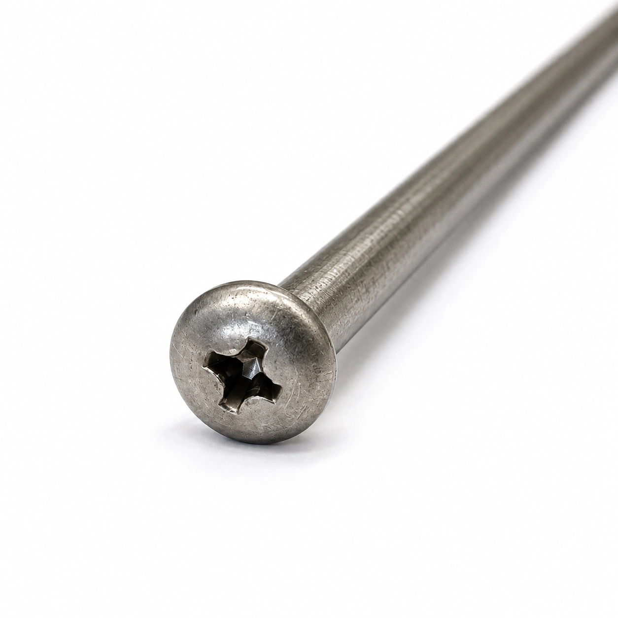
A long Phillips screw is a screw with a cross-shaped drive recess and an extended shank or overall length. “Phillips” identifies the drive system; it does not define the head, thread, material, strength or surface finish.
This page covers machine screws and drawing-defined special fasteners for metal and equipment assemblies. It does not cover long-shaft Phillips screwdrivers, wood screws, drywall screws or self-drilling screws.
There is no universal industry length at which every screw becomes “long.” The practical definition depends on the diameter, length-to-diameter ratio, assembly reach and manufacturing route.
Long Phillips Screw Configurations
Start with the head and shank structure closest to the assembly. The final recess, dimensions, thread, material and finish are confirmed from the drawing.
Long Phillips Pan Head Machine Screws
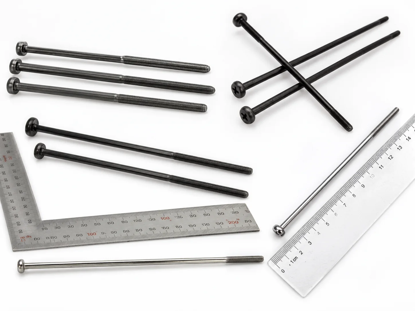
A raised pan head provides an accessible bearing surface for general equipment, enclosure and component assembly. Full-thread and partial-thread configurations can be developed around the required reach and engagement.
- • Pan-head diameter and height
- • Overall and under-head length
- • Full or partial thread
- • Carbon steel, alloy steel or selected stainless grades
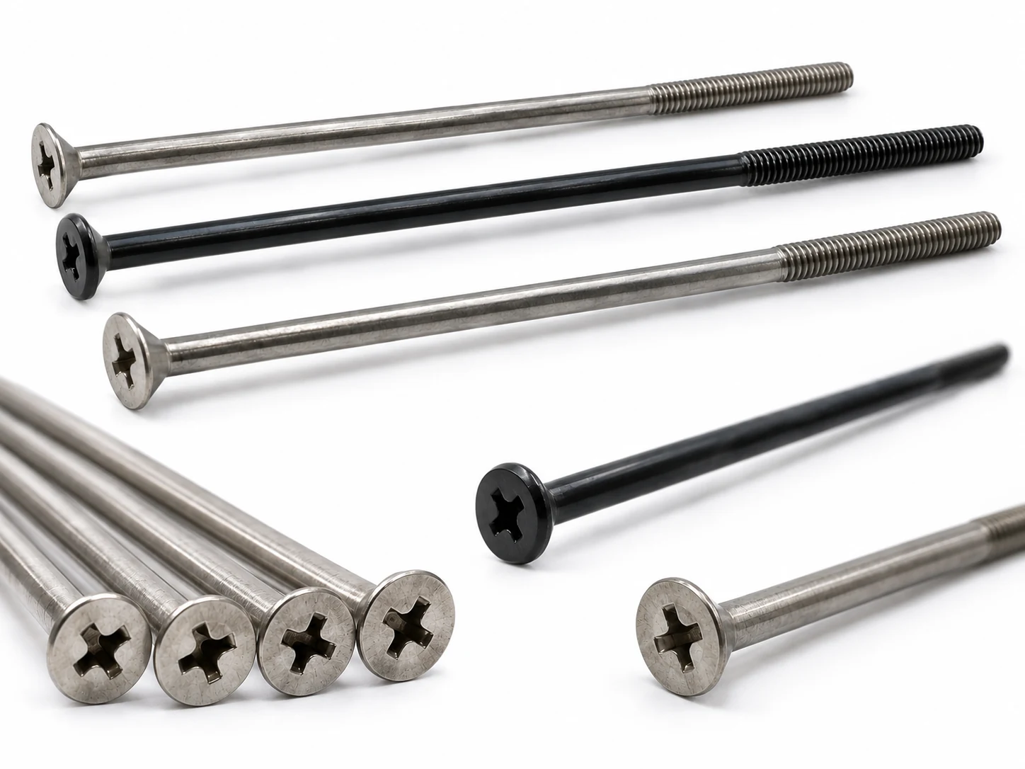
Long Phillips Flat / Countersunk Head Machine Screws
A countersunk head is used where the installed head must sit flush or close to the mating surface. The countersink angle, head diameter and prepared hole must be compatible.
- • Countersink angle and head diameter
- • Length normally measured including the head
- • Recess depth and driver clearance
- • Full or partial thread
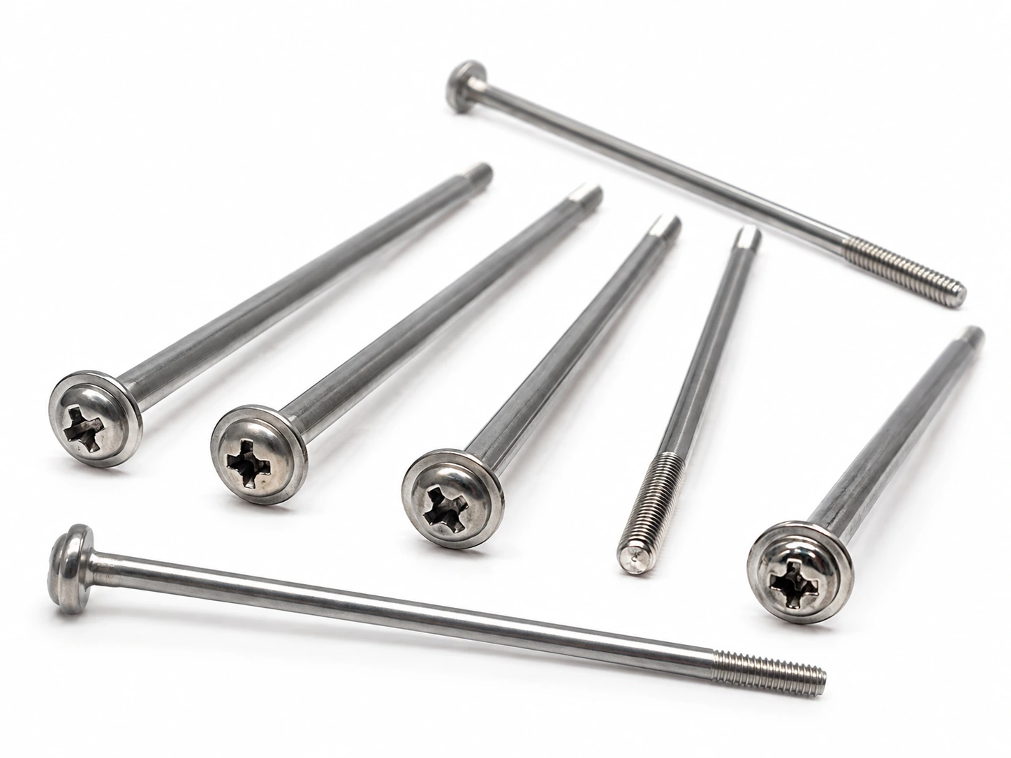
Long Phillips Pan Washer Head Machine Screws
A pan washer head adds a wider bearing area beneath the head. It can be combined with a long plain shank, partial thread, shoulder or drawing-defined under-head geometry.
- • Bearing-face diameter
- • Head and under-head profile
- • Plain-shank or shoulder length
- • Thread length and transition geometry
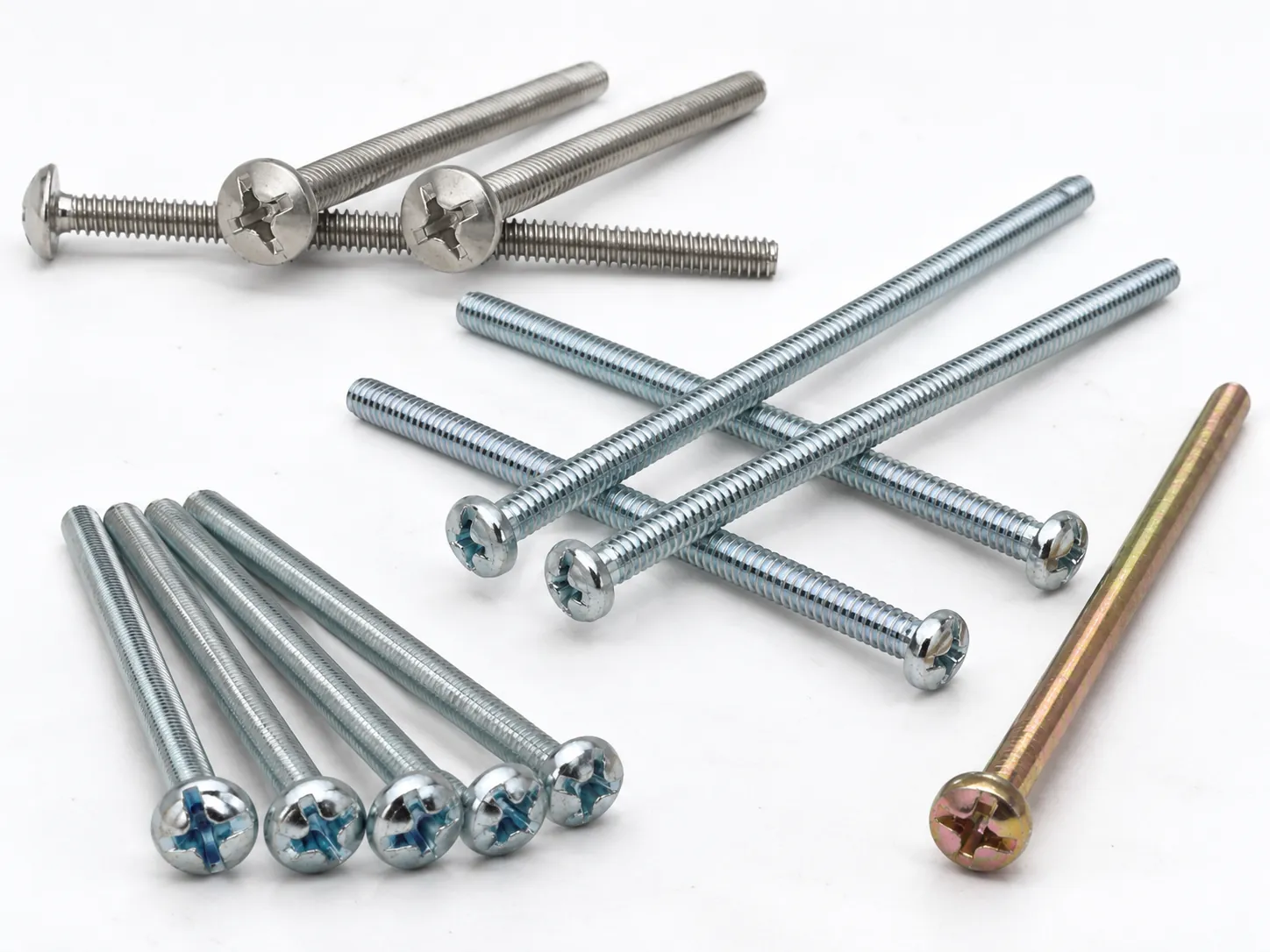
Long Phillips Combination-Drive Machine Screws
A Phillips and slotted combination recess can be evaluated when the drawing requires two compatible tool-engagement paths. The exact recess dimensions and matching tools must be defined.
- • Phillips/slotted recess geometry
- • Head profile and recess depth
- • Matching installation tool
- • Assembly torque conditions
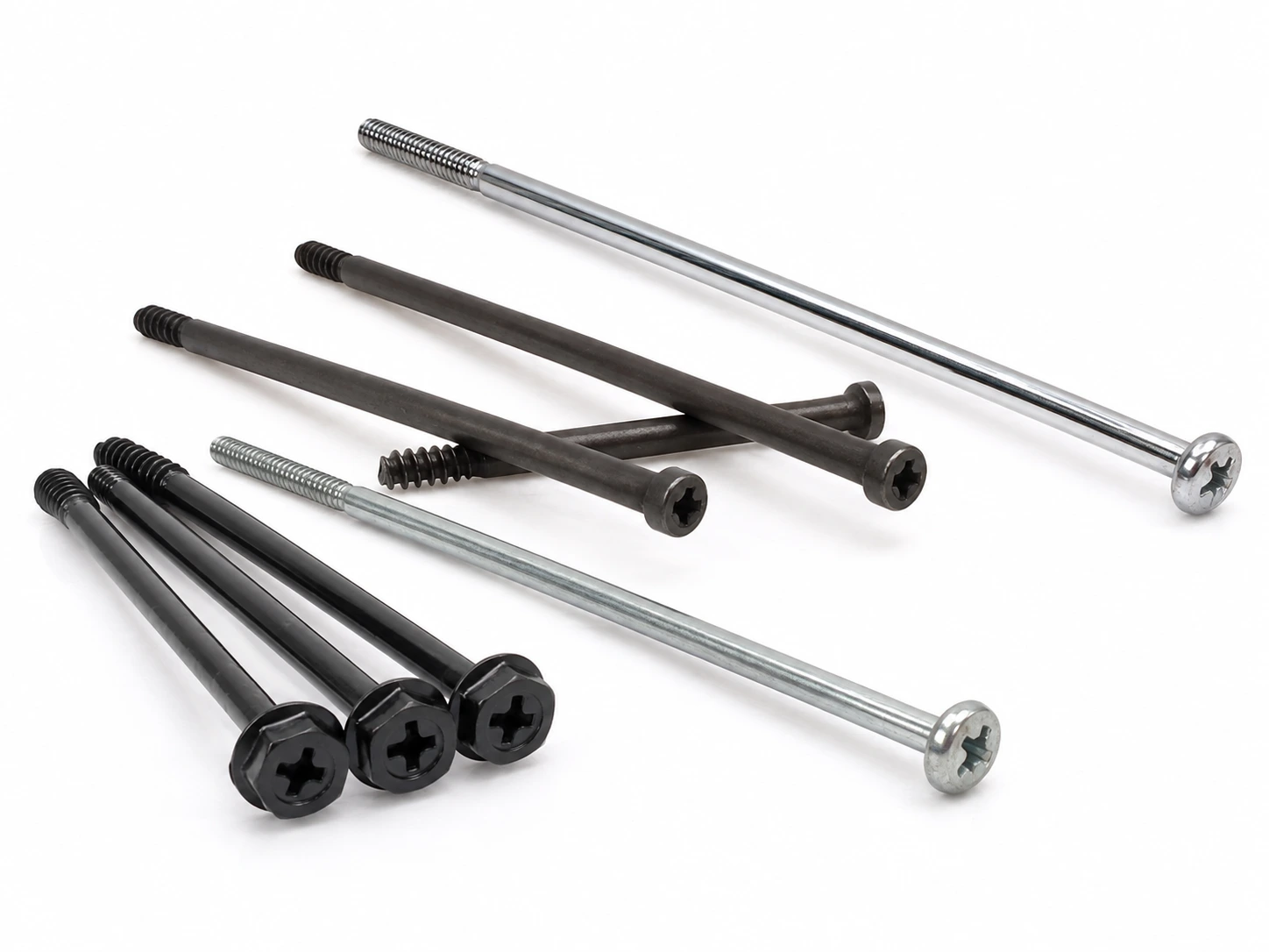
Custom Long Phillips Shoulder & Special-Geometry Screws
For assemblies requiring a controlled shoulder, stepped shank, reduced section, special tip or non-standard head profile beyond a conventional machine screw.
- • Shoulder diameter and length
- • Stepped or reduced-shank geometry
- • Drawing-defined transitions and tolerances
- • CNC secondary machining when required
Compare Long Phillips Screw Head Styles
| Configuration | Typical Assembly Fit | Critical Selection Points | Length Reference |
|---|---|---|---|
| Pan Head | Equipment, panels, housings and general metal assemblies | Head diameter, head height, bearing surface and tool clearance | Usually measured from below the head |
| Flat / Countersunk Head | Prepared countersunk holes requiring a flush installed profile | Countersink angle, head diameter, hole preparation and remaining material thickness | Usually measured including the head |
| Pan Washer Head | Assemblies requiring a wider bearing area beneath the head | Bearing diameter, under-head geometry and mating-surface condition | Usually measured from below the head |
| Combination Drive | Drawings requiring Phillips and slotted tool engagement | Recess dimensions, tool compatibility, head thickness and torque conditions | Determined by the selected head |
| Shoulder / Special Geometry | Location, spacing, guidance or drawing-specific functions | Shoulder diameter, functional length, transitions, runout and critical tolerances | Must follow the approved drawing |
The approved drawing or applicable product standard takes precedence over general measurement practice.
Define the Complete Screw, Not Only the Length
| Nominal Diameter | M1.4–M12, subject to complete design review |
|---|---|
| Overall Length | 2–2000 mm, subject to diameter, geometry, material, tolerance and production-route review |
| Thread System | Metric, inch or drawing-defined machine threads |
| Thread Coverage | Fully threaded, partially threaded or localized thread zone |
| Head Options | Pan, flat/countersunk, pan washer and drawing-specific profiles |
| Drive Options | Phillips, Phillips/slotted combination and reviewed custom recesses |
| Shank Options | Plain, reduced, stepped or shoulder shank |
| Materials | Carbon and alloy steel, stainless steel, titanium, aluminum, copper or brass, subject to project review |
| Surface Finish | Selected according to substrate, appearance, corrosion requirement, friction and dimensional fit |
| Manufacturing Routes | Single-die cold heading, multi-station forming, open-die forming for suitable long screws, thread rolling and CNC secondary machining |
| Inspection | Drawing-based dimensional, thread, recess, material, hardness and project-specific checks |
Not every material, head, diameter and length combination is feasible across the full stated range. Shi Shi Tong confirms the practical route after reviewing the complete drawing.
How to Choose the Right Length and Diameter
Measure the complete clamped stack.
Include every panel, bracket, cover, washer, spacer and controlled gap in the assembled condition.
Define the required thread engagement.
Determine engagement from the mating material, load, nominal diameter, thread form and applicable engineering standard. There is no universal engagement value for every assembly.
Use the correct length reference.
Pan, washer and similar raised heads are commonly measured from below the head. Flat and countersunk heads are commonly measured including the head.
Separate thread length from overall length.
A long screw may need only a short threaded end, a long plain shank or several drawing-defined functional zones.
Check clearance and protrusion.
Confirm tool access around the head and available space beyond the mating thread.
Review the length-to-diameter ratio.
Slender parts may require different forming, handling and inspection planning from shorter screws of the same diameter.
Specify diameter and thread correctly.
For machine screws, use a nominal metric diameter and pitch or an inch diameter, threads per inch and thread class. “Gauge” alone may not provide enough information.
Reduce Cam-Out and Recess Damage During Assembly
A longer screw does not require a longer driver bit in every assembly, but it still requires the correct Phillips size, full bit engagement and controlled installation. Cam-out risk increases when the bit, recess, alignment, speed or torque is mismatched.
| Assembly Risk | Common Cause | Practical Control |
|---|---|---|
| Bit lifts out of the recess | Incorrect bit size or incomplete seating | Match the specified Phillips size and seat the bit fully before rotation |
| Recess edges deform | Worn bit, excessive speed or excessive torque | Replace worn tools and validate the torque and speed on representative samples |
| Driver enters at an angle | Restricted access or poor fixture alignment | Keep the driver axis aligned with the screw axis and review tool clearance |
| Coating interferes with the recess | Excess coating thickness or recess accumulation | Define coating allowance and inspect recess fit after surface treatment |
| Custom low-profile head has insufficient recess depth | Head geometry and recess volume were not reviewed together | Confirm head height, recess depth, drive size and required installation torque before tooling |
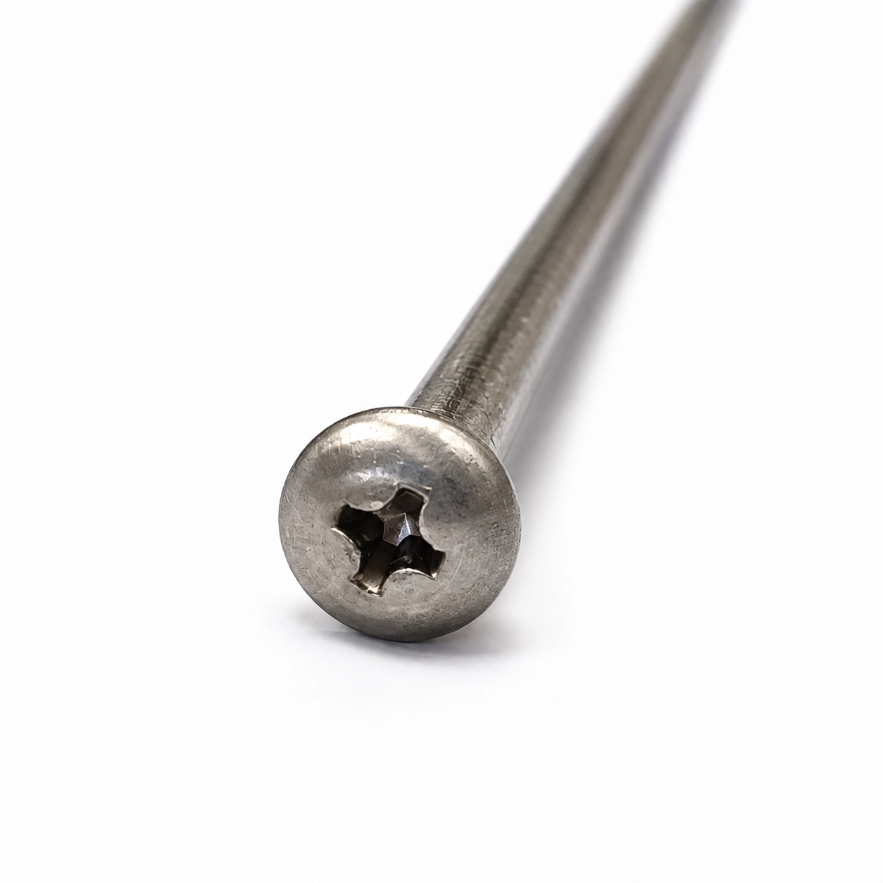
Where recess fit or assembly torque is critical, identify it on the drawing or inspection plan. Shi Shi Tong can evaluate recess depth, geometry and project-specific torque checks when they are defined as controlled requirements.
Compare Materials by Load, Environment and Finish
| Material Direction | Useful Characteristics | Points to Review |
|---|---|---|
| Carbon Steel | Forming flexibility, available strength classes and a wide range of surface treatments | Strength class, heat treatment, corrosion system, coating thickness and thread fit |
| Alloy Steel | Suitable for selected projects requiring defined strength or hardness | Exact grade, heat treatment, hardness, hydrogen-embrittlement controls and finish compatibility |
| 304 / 316 Stainless Steel | Corrosion resistance without relying only on a plated carbon-steel surface | Exact grade, chloride exposure, galling risk, strength requirement and compatible finish |
| Brass and Copper Alloys | Electrical, appearance or material-specific applications where the drawing supports them | Exact alloy, strength, conductivity, surface appearance and forming feasibility |
| Aluminum or Titanium | Selected projects requiring lower weight or special material properties | Exact grade, thread durability, galvanic contact, head-forming feasibility and quantity |
Material durability cannot be judged from the material name alone. The exact grade, mechanical condition, mating materials, load, temperature, moisture, chemicals and maintenance conditions must be considered together.
Selecting a Finish for Outdoor or Corrosive Conditions
Outdoor suitability is a system decision. Start with the base material, then define the pretreatment, coating or conversion layer, thickness, topcoat, contact materials, exposure and acceptance test.
Potential project routes may include zinc systems, zinc-nickel, electrophoretic coating, black oxide, passivation, PVD or other material-compatible treatments. Availability depends on the exact substrate and drawing.
Tip 1:
Do not specify only “durable,” “rustproof” or “outdoor grade.” State the required coating standard, thickness, color or appearance sample, test method and failure criterion.
Tip 2:
A salt-spray result does not directly predict the number of years a screw will last outdoors.
Control the Details That Change Assembly Results
The standard screw is too short.
A custom overall length can be combined with a drawing-defined thread zone and plain shank instead of extending the thread without reviewing its function.
The Phillips recess strips during installation.
Drive size, recess depth, head geometry, coating allowance, tool alignment and assembly torque must be treated as one installation system.
The long shank does not fit the assembly consistently.
A high length-to-diameter ratio can affect forming, handling and inspection. Straightness, runout, shank diameter and critical transitions should be defined where they affect fit.
Surface treatment changes the thread or recess fit.
Coating thickness may change thread engagement, recess clearance and critical diameters. The drawing and inspection plan should identify which dimensions apply after treatment.
A Manufacturing Route Selected for the Complete Geometry

Drawing and Application Review
Review the head, recess, overall length, thread zones, shank, material, finish and controlled tolerances.
Forming Route Selection
Evaluate single-die cold heading, multi-station forming or open-die forming for suitable extra-long configurations.
Thread and Secondary Features
Use thread rolling and CNC secondary machining where the design requires steps, shoulders, reduced sections or special ends.
Surface Treatment Coordination
Review treatment compatibility with the material, thread fit, recess, appearance and required test.
Inspection Planning
Match the inspection method to the drawing-defined functional features before sample approval and repeat production.
Why Use a Drawing-Based Long Screw Program
-
Head, drive and length are reviewed together. This reduces ambiguity between the selected Phillips recess, head thickness and required installation method.
-
Thread coverage follows the assembly function. Full thread, partial thread, localized end thread and shoulder configurations can be evaluated separately.
-
Material and finish remain specification-driven. The selected system is reviewed for strength, corrosion, appearance, friction and dimensional fit.
-
Critical features receive project-specific inspection. The inspection plan can identify the dimensions, thread, recess, material, hardness or assembly checks that matter to the part.
Applications for Long Phillips Machine Screws
These are representative assembly directions rather than universal approvals. Final suitability depends on the drawing, joint, load and operating environment.
Machinery and Production Equipment
Long-reach fastening for selected guards, brackets, frames and internal equipment components.
Automation and Positioning Assemblies
Drawing-defined lengths, shoulders and thread zones for fixtures, sensors and positioning components.
Electrical and Electronic Enclosures
Phillips-driven fasteners for selected panels, covers, housings and internal mounting structures.
Energy-Storage Equipment
Custom long machine screws for selected battery-pack brackets, enclosures and component assemblies.
Instruments and Precision Equipment
Special head, shank or shoulder configurations for assemblies where access, location and controlled geometry matter.
Quality and Inspection for Long Phillips Screws
Long screws must be checked as functional components rather than by overall length alone. Shi Shi Tong builds the inspection plan around the drawing and the characteristics that affect assembly.
- ✓ Overall, under-head and functional-zone dimensions
- ✓ Head diameter, head height and recess depth
- ✓ Thread pitch and GO/NO-GO verification
- ✓ Shoulder, shank, transition and drawing-defined geometry
- ✓ Concentricity, angle, radius and optical measurement where applicable
- ✓ Rockwell or Vickers hardness when required
- ✓ Material verification and project-specific tests
- ✓ Torque checks when defined by the project
Supplier Capabilities:

Long Phillips Screw Selection Guide
What are the common sizes of long Phillips screws?
How do I choose the right length and diameter?
How can I drive a long Phillips screw without stripping the recess?
How should I compare long Phillips screws by material and durability?
Which long Phillips screws are suitable for outdoor use?
Are long Phillips screws suitable for heavy-duty construction?
Can I buy long Phillips screws online with fast shipping?
Do you supply long Phillips wood screws or drywall screws?
Prepare a Usable Long Phillips Screw RFQ
For an efficient review, provide a drawing whenever possible. Identify the features that affect fit, installation and inspection.
- • Nominal diameter and thread
- • Overall length and measurement reference
- • Head profile and dimensions
- • Phillips or combination-drive designation
- • Thread length and plain-shank length
- • Material grade and mechanical requirements
- • Surface finish and corrosion-test requirement
- • Critical tolerances and inspection criteria
- • Application and mating components
- • Estimated production quantity
A physical sample can support an initial review, but a dimensioned drawing should define the final acceptance requirements.
Send Us Your Long Phillips Screw Drawing
Our team will review the head, recess, length, thread zones, material, finish, critical tolerances and inspection requirements before confirming the manufacturing approach.
Attach a drawing and identify the dimensions or assembly conditions that cannot change.