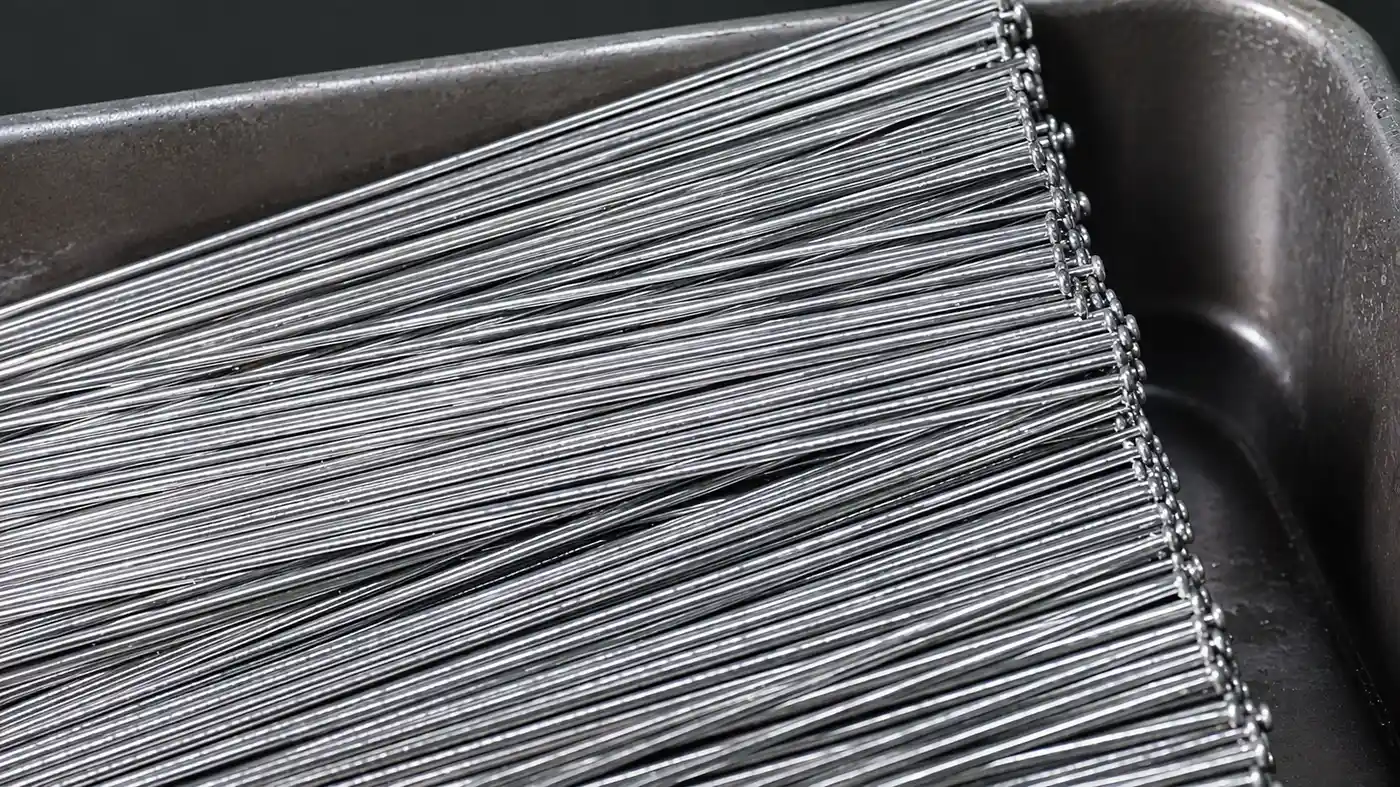

Custom Low-Profile Screws Manufacturer
Shi Shi Tong manufactures drawing-based low-profile screws in Shenzhen, China, for assemblies with limited head clearance. We review the head envelope, drive engagement, thread or stepped shank, material and finished fit as one part specification.
Lower head projection. Geometry matched to the connection.
Choose the Low-Profile Screw Geometry Your Joint Needs
Start with the connection: a tapped receiver, a tighter height envelope, a stepped interface or a reviewed self-tapping design. These four directions are assessed from the drawing rather than offered as one interchangeable stock range.
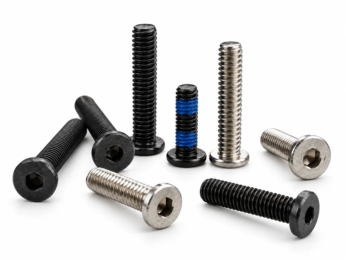
Low-Head Socket Screws
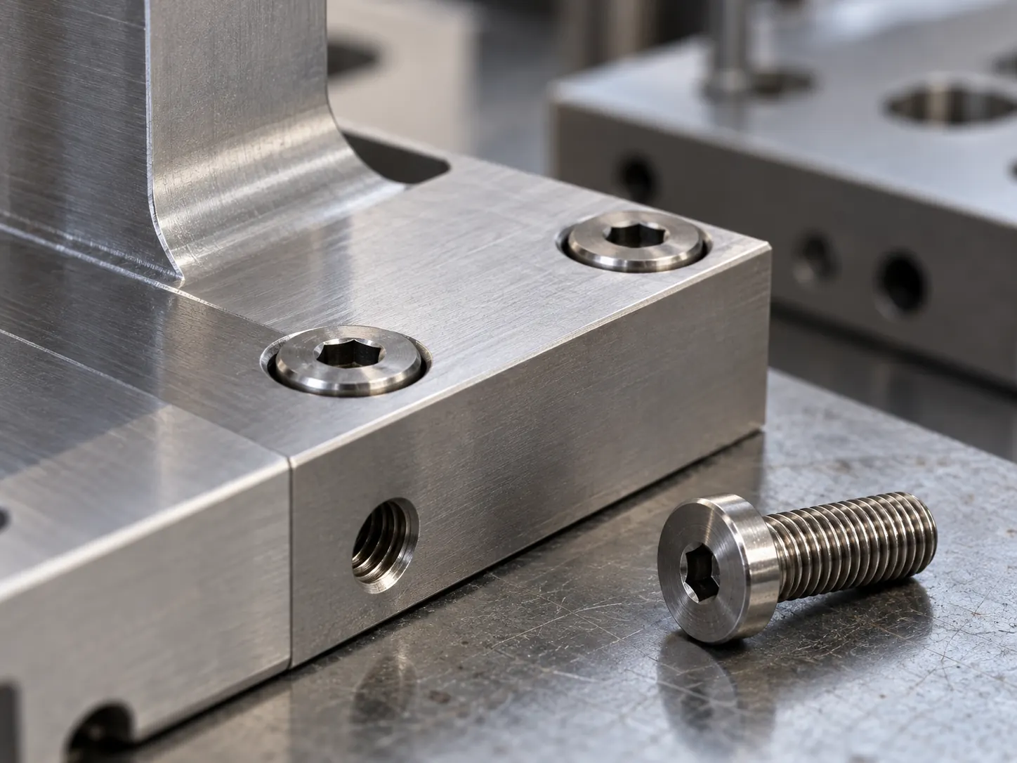
Reduced-height heads with hex-socket drive geometry for machine-threaded connections. Head height, diameter, recess engagement and the material beneath the recess are reviewed together.
Consider this direction when the screw must clear a nearby component while retaining suitable driver access.
Low-head hex-socket screw samples with machine threads.
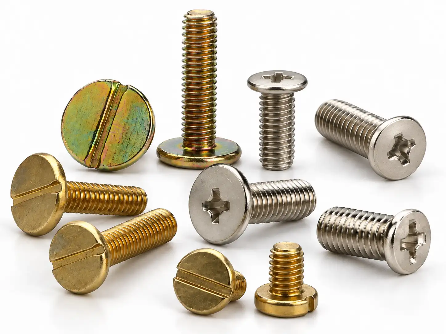
Ultra-Low Head Machine Screws
Thinner head forms for more restricted vertical space. The available bearing area, drive depth and head-to-shank transition must still suit the connection and its installation requirements.
Consider this direction when a low head still projects too far above the intended seating surface.
Ultra-low head reference with a six-lobe recess and a center pin.
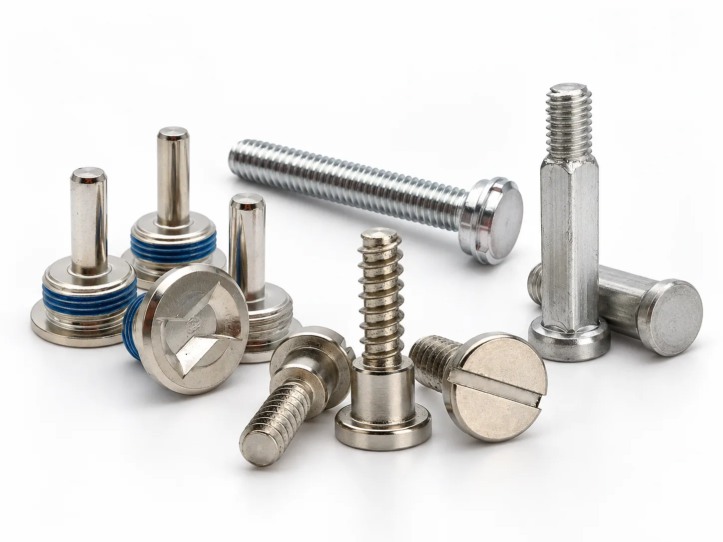
Low-Head Shoulder & Stepped Screws
Low head projection combined with a shoulder or stepped rod geometry. Rod shape, transition positions, thread start and the axial stack define how the part seats in the assembly.
Consider this direction when head clearance and a defined rod interface must be controlled on the same part.
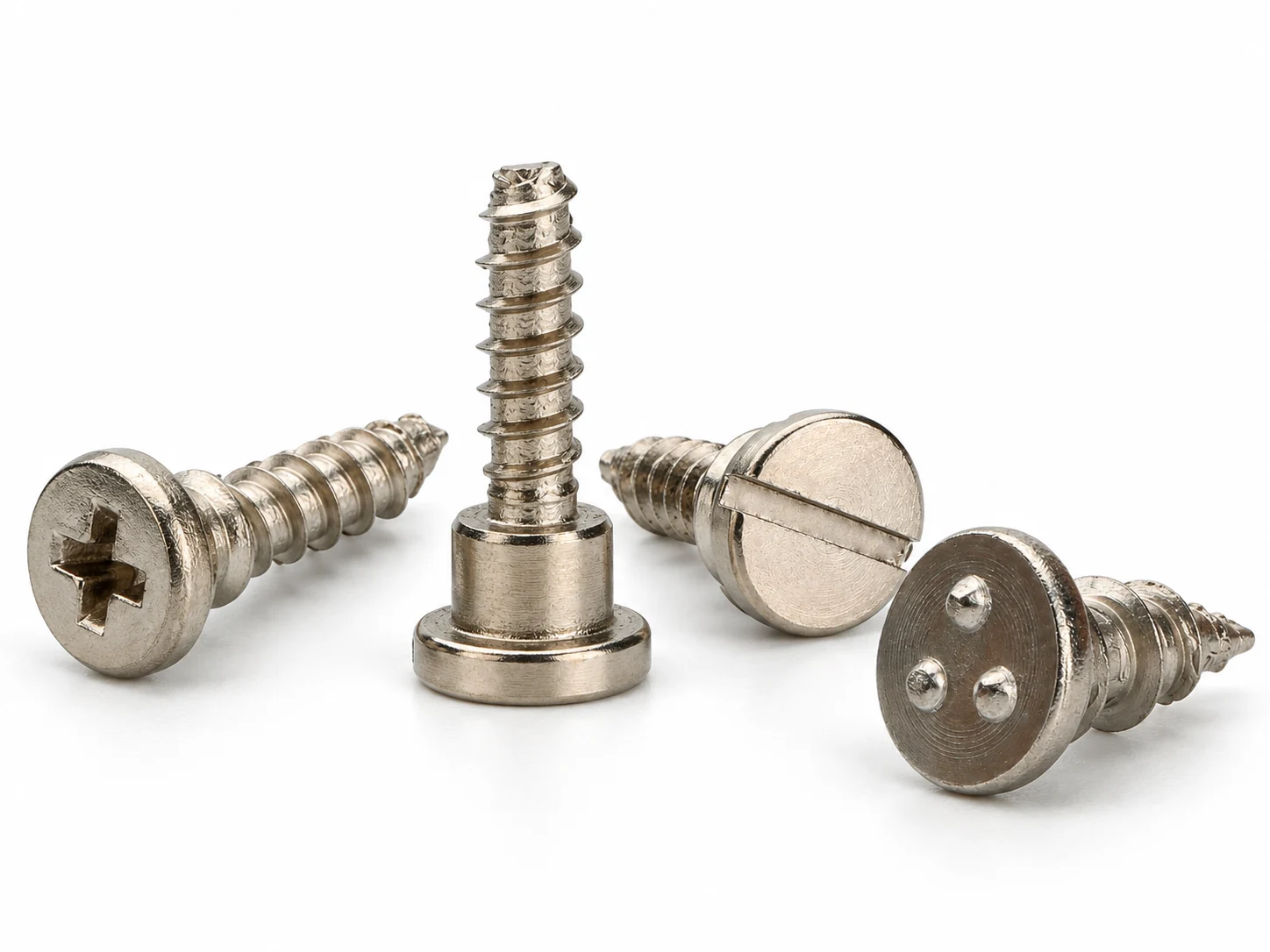
Low-head sample with a faceted shank and a stepped transition to the thread.
Low-Profile Self-Tapping Screws
Low head forms paired with a self-tapping thread for a suitable untapped receiver. The receiving material, pilot-hole geometry, engagement and installation behavior determine whether the proposed design is appropriate.
Consider this direction when the connection calls for self-tapping engagement rather than a specified mating machine thread.
Low-head sample with a pointed self-tapping thread and an under-head collar.
Low Head Height Does Not Automatically Mean Flush Installation
A low-profile screw reduces the head height selected for a connection. Its installed projection also depends on the mating seat, any washer or spacer and the surface used as the reference. A flat-topped thin head can still sit above that surface.
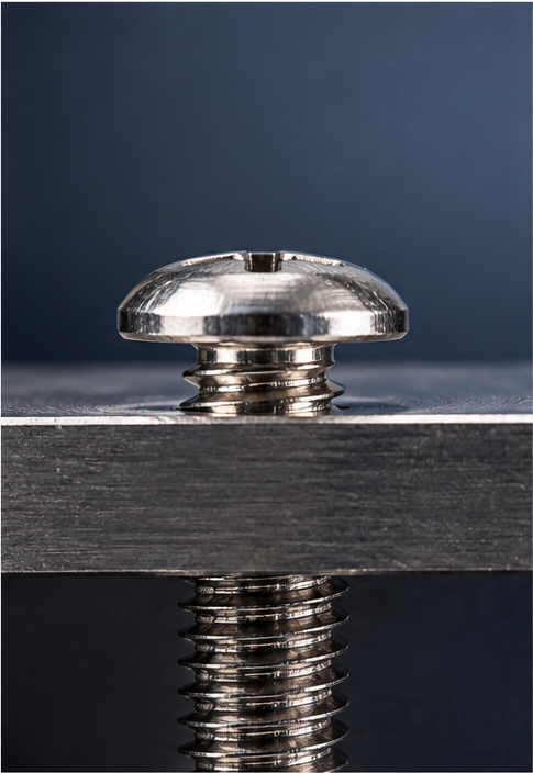
Conventional Head Above the Surface
The head projects from its bearing surface. The surrounding assembly must provide enough space for both the installed head and the tool.
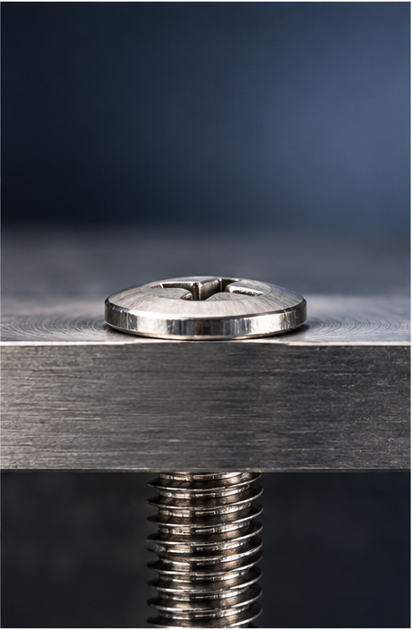
Low Head Above the Surface
A lower head can reduce vertical interference without a conical countersink. Its diameter and bearing face must still fit the joint.

Countersunk Head in a Matching Seat
A flush position depends on the countersink and head geometry matching. The seat preparation removes material from the receiving component and needs its own dimensional definition.
Head height controls vertical space. Head diameter controls radial space. Reducing one does not automatically reduce the other.
Schematic Labels: Reference surface / Bearing face / Installed projection / Head diameter / Matching countersink
Seating concepts illustrated schematically; not to scale.
Specify the Head Envelope and the Working Connection
A thread size alone cannot define a low-profile screw. The drawing needs to connect the head and drive to the engagement, seating surface and any controlled rod section.
Labels: Head height / Head diameter / Drive depth / Length datum / Effective thread / Step position
| Drawing feature | Why it matters |
|---|---|
| Head height and maximum installed projection | Distinguishes the part dimension from the assembly clearance limit. |
| Head diameter and bearing face | Defines radial clearance and the contact geometry beneath the head. |
| Drive type, size and recess depth | Defines the tool interface and the remaining material in the head. |
| Thread system, pitch and fit | Matches a machine-threaded receiver, or defines the separately reviewed self-tapping form. |
| Length datum and effective engagement | Distinguishes the stated screw length from the thread that actually engages the receiver. |
| Shoulder, step and transition positions | Defines where a plain section sits and where the thread can begin working. |
| Material, condition, finish and critical tolerances | Sets the finished-part requirements used for manufacturing and acceptance. |
No single minimum head height or universal size range covers every material and geometry. Shi Shi Tong reviews the requested combination, including how the critical dimensions will be measured after the agreed finishing processes.
Review Custom Screw Tolerances →A Lower Head Still Needs a Working Drive
A low head must fit both the assembly and the driver. Making the recess deeper may improve engagement, but it also changes the material remaining beneath the recess and around the head-to-shank transition.
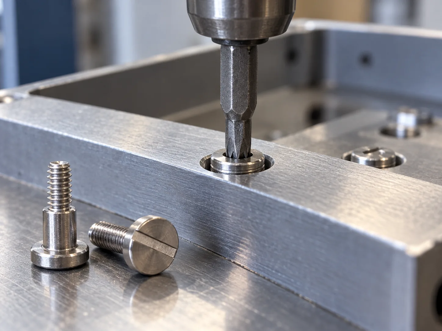
Schematic Labels: Bit engagement / Recess floor / Head-to-shank transition / Tool approach
Match the Recess to the Actual Tool
Hex-socket and six-lobe drives need the correct bit size, usable engagement depth and approach clearance. A recess with a center pin also needs a compatible tool. A driver that cannot seat fully can damage the interface before the intended joint condition is reached.
Review the Remaining Head Section
The recess, head height and transition must be considered together. A thin head is not automatically equivalent to a taller head of the same thread size in drive capacity or load behavior. The proposed geometry needs to suit the installation and service requirements.
Check the Installation Path
The screw may clear the finished enclosure while the bit holder cannot reach it during assembly. Review tool approach, nearby walls and the assembly sequence as well as the final head position.
Choose the Thread From the Receiving Component
Head clearance does not decide the thread type. A low-profile machine screw and a low-profile self-tapping screw rely on different receiving geometry and cannot be selected from head appearance alone.

Machine-Threaded Connection
Match the screw to the specified tapped hole, insert or nut. Thread system, pitch, fit and effective engagement determine compatibility. Any plain shank or transition must sit clear of the working female thread, and a blind hole must allow the required seating without the screw bottoming first.
Labels: Specified mating thread / Effective engagement / Plain section / Blind-hole clearance

Reviewed Self-Tapping Connection
Define the receiving material, local thickness or engagement depth, pilot-hole geometry and intended thread form. Evaluate thread formation, seating and stripping behavior in the actual receiver. A successful fit in one material or pilot hole does not establish the same behavior in another.
Labels: Receiving material / Specified pilot hole / Self-tapping engagement / Seating surface
The self-tapping sample shown on this page has a pointed end; it is not a self-drilling point. Drilling capability, sheet thickness and pull-out performance are separate requirements and are not inferred from a low head.
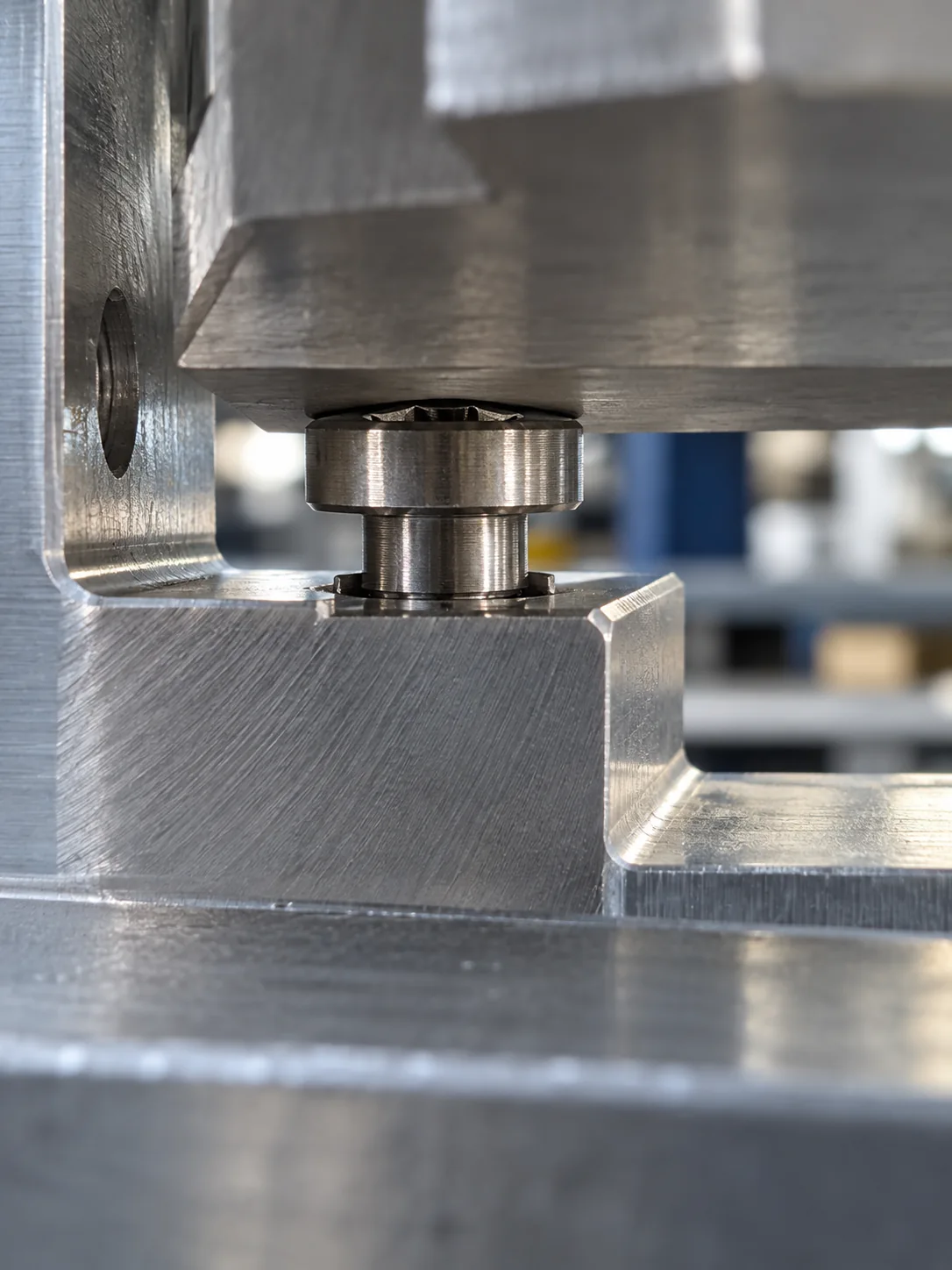
Labels: Head clearance datum / Clamping face / Shoulder stop / Step position / Thread start / Mating clearance
Head Clearance and the Stepped Stack Need Separate Datums
A low-head shoulder or stepped screw combines two design tasks: clearing the space above the head and controlling the interface below it. The head can meet its height limit while the rod geometry still prevents the intended seating or engagement.
Define What Seats First
State whether the head bearing face should clamp the part or a shoulder should stop against another surface. If the shoulder stops first, the joint may not receive the intended clamping action.
Locate the Step and Thread Start
The axial position of each transition determines which component surrounds the plain section and how much thread can engage. Nominal screw length does not describe this stack by itself.
Specify the Rod Shape and Fit
A round shoulder, a faceted shank and a stepped diameter perform different interface roles. Describe the required shape and clearance; a pictured shoulder form does not establish a sliding or precision-bearing fit.
Control the Functional Surfaces
Use the drawing to identify the seating face, locating section and any relationship between axes or faces that affects the assembly. Acceptance should follow those datums rather than an overall dimension alone.
Select the Material and Finish for the Actual Joint
Steel, stainless steel, titanium, aluminum, copper and brass are material directions within Shi Shi Tong’s custom screw work. The exact grade, low-head geometry and manufacturing route are reviewed for each part; they do not form one unrestricted combination list.
| Material direction | Selection focus |
|---|---|
| Steel | Required mechanical properties, condition and surface protection for the specified connection. |
| Stainless steel | Exact grade, corrosion exposure, mating materials and installation behavior. |
| Titanium | Exact grade, feasible head and drive geometry, surface condition and mating-thread behavior. |
| Aluminum, copper or brass | The particular alloy, forming or machining route, bearing conditions and required function. |
Confirm the Finished Fit
A specified coating or surface process can affect the recess, thread and controlled rod interface. Evaluate critical fit in the finished state, especially where the design leaves little clearance. A black or metallic appearance in a sample photograph does not identify its grade or treatment.
Material selection does not make a head sit flush. The head and mating seat determine the position.
Where Low-Profile Screw Geometry Makes a Difference
Low-profile screws are considered where head projection interferes with the surrounding design. These assembly contexts illustrate selection questions; the suitable part still depends on the joint geometry and requirements.
Compact Electronics and Housings
A cover, enclosure wall or nearby component can restrict the space above the head. Review the installed envelope and tool access together so that a lower head can fit the intended assembly sequence.
Thin Panels and Covers
A deep countersink may conflict with the available panel thickness. A thin head above the surface can be a design direction when the joint permits it, but head diameter, bearing area and the allowable projection still need review.
Components Beside Moving Parts
A neighboring part may travel past the fastener. Check the full motion envelope and tolerance stack rather than the clearance in one static position; reducing head height addresses only one part of that interference review.
Compact Stepped Connections
A rod interface may need a controlled step while the head must clear a cover. The seating sequence, step position and effective thread engagement determine whether those requirements can coexist on the proposed part.
A low head alone does not establish a load rating, sealing function or safety benefit. Define those requirements separately where the connection needs them.
Low-Head Geometry Reviewed With the Manufacturing Route
Shi Shi Tong is a custom screw manufacturer in Shenzhen, with screw-manufacturing roots dating to 1998. Our work includes thin and special head forms, custom recesses, shoulders and stepped rod geometry. For a low-profile screw, the route is assessed around the material and functional features rather than selected from the head name alone.
Geometry and Tooling Review
Review the thin head, recess, bearing face and head-to-shank transition together. Tooling assessment considers material flow into broad, thin sections and the material left beneath the drive. These demands differ from a conventional head even when the thread size is unchanged.
Forming and Machining Assessment
Assess a forming route, turning or necessary secondary operations against the material and geometry. Rod steps, critical interfaces and the required finished state can influence where each operation belongs in the production plan.
Sample and Batch Control
Use the agreed drawing and sample requirements to confirm critical geometry and assembly fit. Carry the approved specification and inspection points into repeat production, including protection of thin heads and defined interfaces during handling and packing.
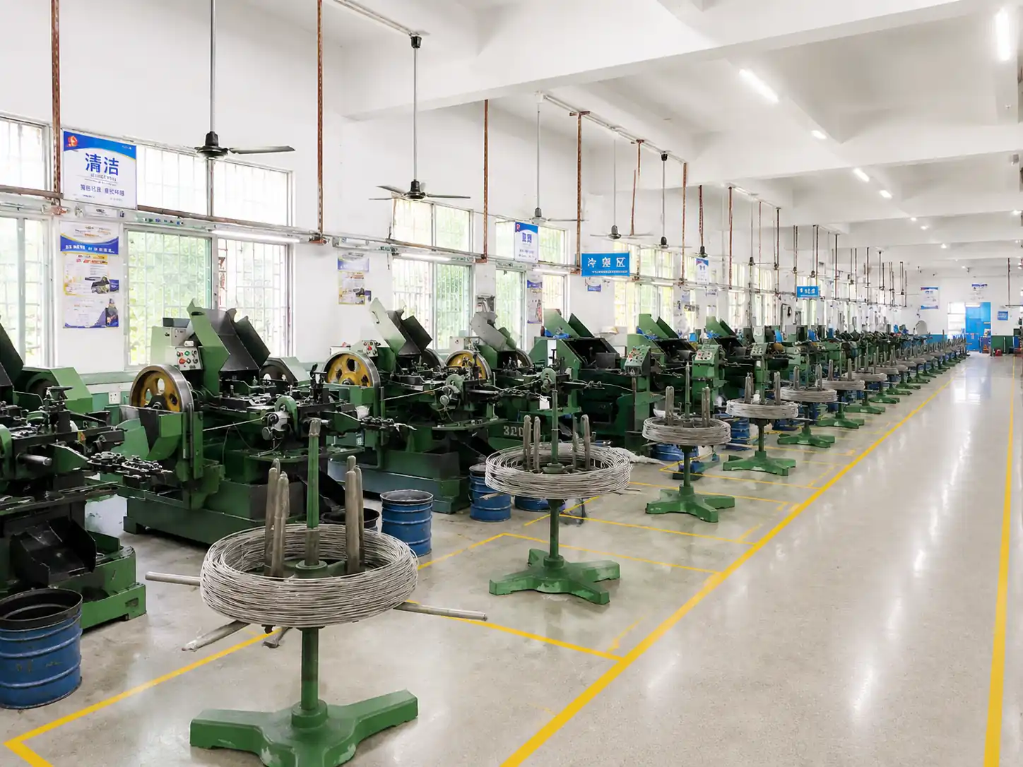
Shi Shi Tong screw production floor in Shenzhen
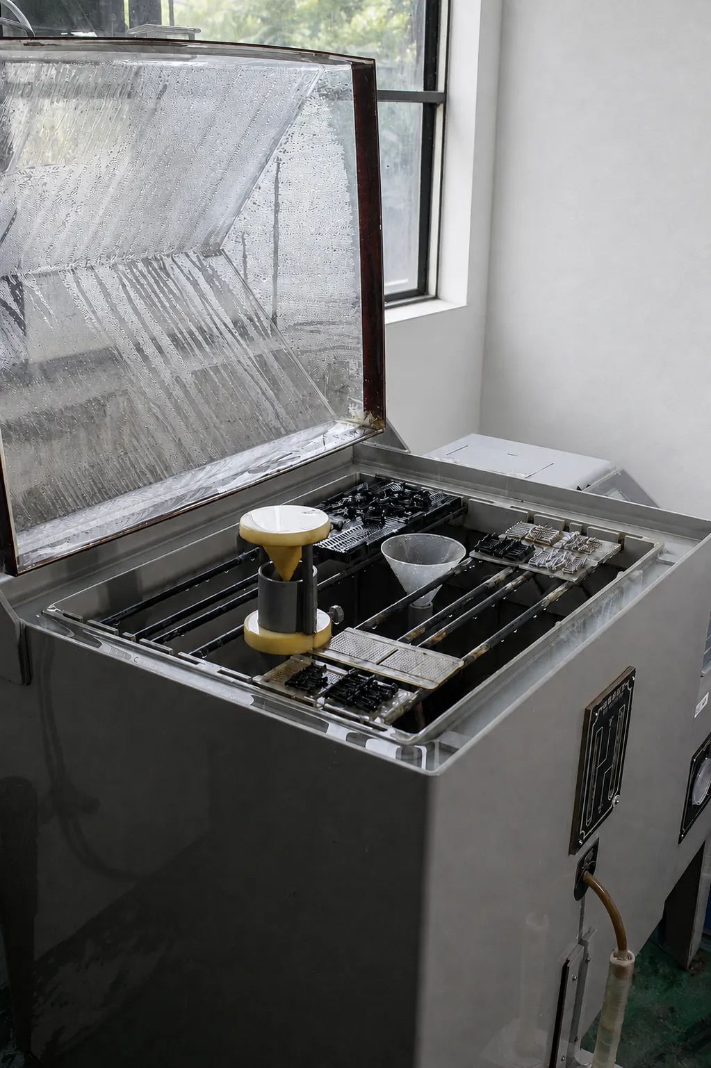
Inspect the Features That Control Clearance and Fit
For a low-profile screw, acceptance should connect the dimensions to the way the part seats, engages the driver and meets the receiver. Shi Shi Tong reviews the inspection scope with the drawing and order requirements.
Head and Rod Geometry
Check the specified head height, diameter, recess, step positions and transitions using methods appropriate to the feature. Profile inspection can support geometric review; the applicable tolerances and measurement basis come from the agreed drawing.
Thread and Drive Interfaces
Use suitable gauges or mating checks for the specified thread and recess. Confirm critical interfaces in the required finished condition. Dimensional conformity and actual assembly behavior are related, but neither should be assumed from a photograph alone.
Assembly and Required Evidence
Where required, agree on checks for seating, driver engagement, torque or other functional requirements using the actual connection. Dimensional records, material documentation and any specified test evidence are arranged to the agreed scope, with the source of specialized testing identified for the project.
The pictured equipment illustrates company inspection activities. It does not establish a material grade, measured result or performance rating for every low-profile screw.
Review Quality Control and Documentation →Low-Profile Screw Buyer Guide
Use these answers to distinguish head descriptions, size information, custom sourcing and installation requirements.
Questions
- 1. Are pan head screws low profile?
- 2. What does “low-profile flat head screw” mean?
- 3. What does M5 tell me about a low-profile screw?
- 4. Where can I source low-profile screws for electronics or miniature assemblies?
- 5. How do I install a screw for a flush finish?
- 6. Can I use a standard tightening torque for a low head?
Are pan head screws low profile?
Not automatically. “Pan head” describes a head form; it does not establish the maximum height permitted in your assembly. Compare the actual head height and diameter with the reference surface, nearby components and available tool space. If an existing pan head interferes, a lower design may help, but its drive and bearing geometry must still suit the connection. Select from dimensions rather than the head name alone.
What does “low-profile flat head screw” mean?
The phrase can refer to a thin, flat-topped head above the surface or to a countersunk flat head intended for a matching seat. Those are different seating geometries. A photo of a flat top does not show whether the underside is conical, whether a countersink is needed or whether the installed head will be flush. Identify the underside profile, head dimensions and mating seat on the drawing before selecting a replacement.
Compare the Seating Concepts →What does M5 tell me about a low-profile screw?
M5 identifies a nominal 5 mm metric thread diameter. It does not define the head height, head diameter, screw length, drive, material or finished fit. Confirm the pitch and mating thread requirements, then add the head envelope and the length datum used on the drawing. A full or partial thread and any shoulder or step also affect the engagement. The same nominal thread size can therefore describe several different low-head designs.
Where can I source low-profile screws for electronics or miniature assemblies?
Use a stock supplier when a defined catalog part meets the complete requirement. For a custom head envelope, recess, step or finished interface, compare manufacturers against the same drawing and acceptance scope. Shi Shi Tong reviews drawing-based low-profile screw projects in Shenzhen. “Micro-profile” describes a low head; it does not by itself establish a miniature thread diameter. If the thread size is also very small, confirm the material, head construction, handling and inspection requirements together.
For a quotation, include the critical clearance, material direction, quantity and required inspection. Tooling, process choices and finished-fit requirements affect the commercial assessment.
Explore Micro Screw Requirements →How do I install a screw for a flush finish?
Start with a head and mating seat designed for the required final position. Check the seat dimensions, burrs, any washer or spacer, available engagement and clearance at the end of the hole. Use the correct driver and the agreed installation method, then verify the actual protrusion from the reference surface. Tightening a flat-topped low head harder does not turn it into a countersunk joint; the material choice alone cannot create a flush seat either.
Can I use a standard tightening torque for a low head?
Not from the thread diameter alone. The acceptable installation condition depends on the material, head and recess geometry, surface state, mating thread and joint requirement. A value developed for a taller head may exceed the drive or head capability of a thin design. Distinguish the intended tightening condition from drive failure, screw breakage and receiver stripping. For a self-tapping connection, assess thread formation and seating behavior in the actual receiver. Agree on the installation limits through the applicable specification and joint validation.
Review Inspection and Acceptance →Request a Low-Profile Screw Review
Share a drawing, a clear sample reference or the dimensions you already know. Include the permitted head projection, drive, thread or step geometry, receiving component, material or finish and estimated quantity so we can review a suitable manufacturing direction.