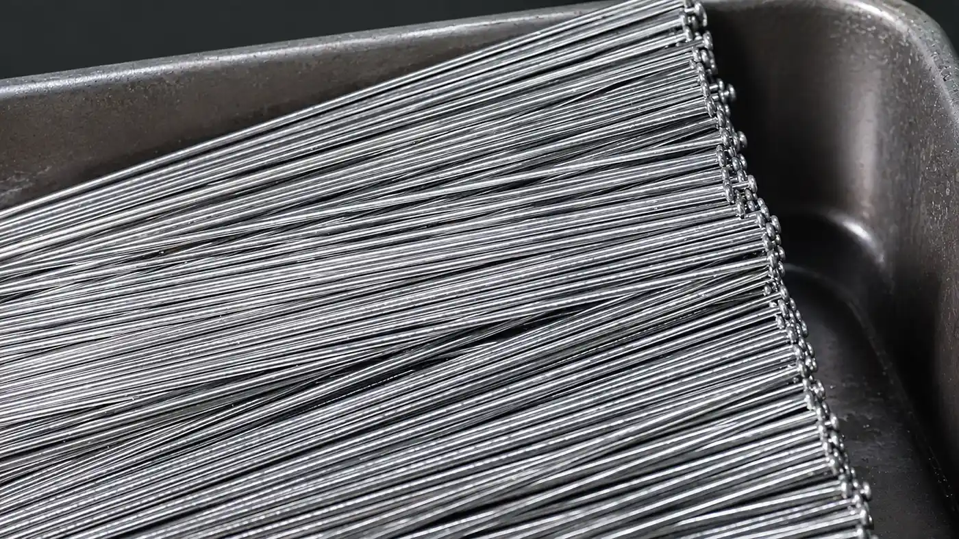

Custom Thread Locking Screws Manufacturer
Shi Shi Tong manufactures custom thread locking screws with pre-applied treatments specified for the assembly. Compare six head styles, then coordinate the thread, coating location, material and finished condition for your joint.
- Six head styles for different installation requirements
- Drawing-defined coating position and coverage
- Screw manufacturing and inspection planned together
Choose the Head Style for Your Assembly
Thread locking screws combine the required screw geometry with an additional locking treatment. The head determines the bearing interface and tool access; the specified treatment addresses the thread-locking requirement.
Our custom configurations include the following head styles. Dimensions, materials, finishes and treatment combinations are reviewed for each part.
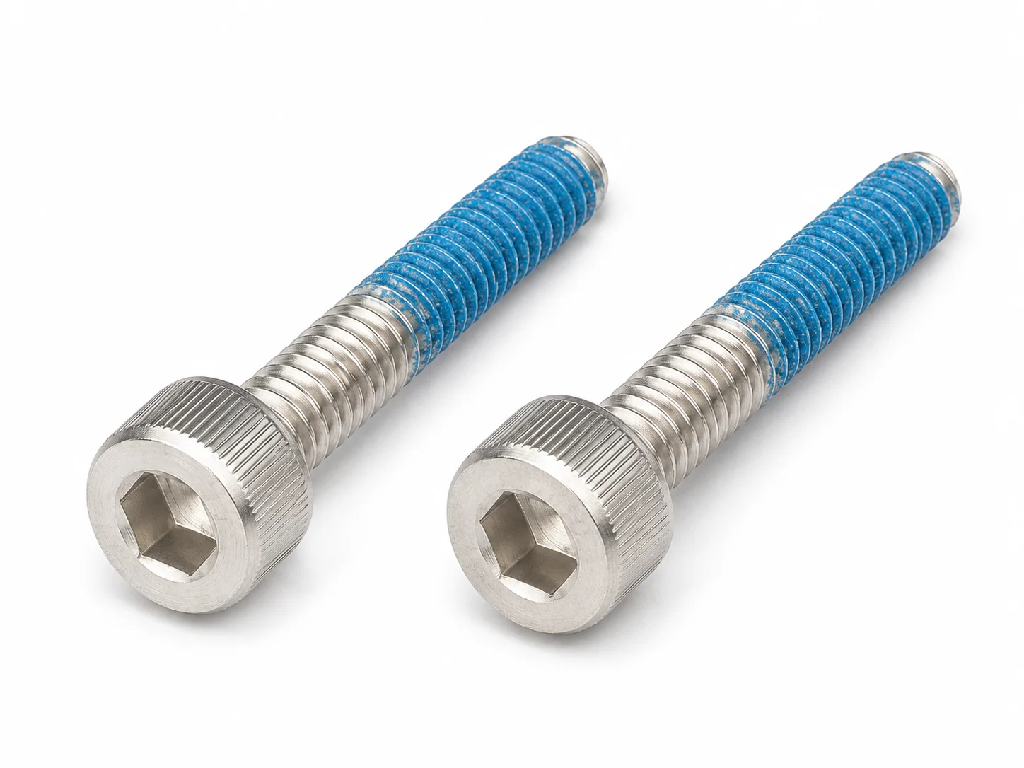
Thread-Locking Socket Head Cap Screws
A cylindrical head with an internal hex drive. Review head height, counterbore clearance and driver engagement where the tool approaches along the screw axis.
Selection focus: head height, counterbore diameter and tool access.
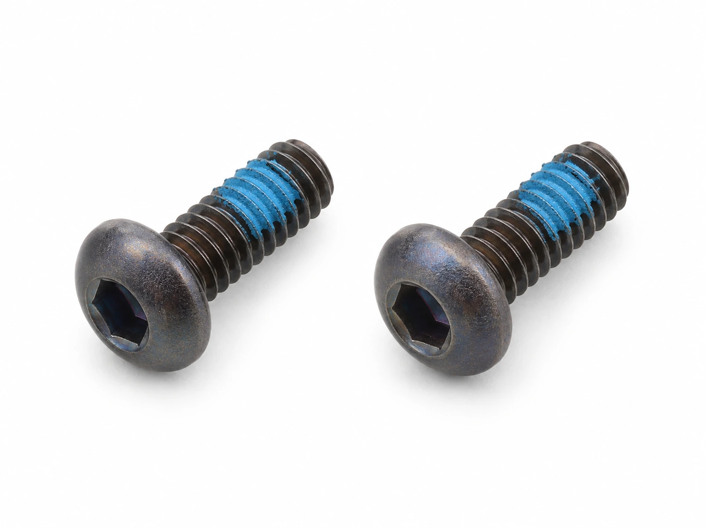
Thread-Locking Button Head Screws
A rounded head for assemblies requiring a lower projecting profile. Match the head diameter, drive engagement and bearing surface to the available installation space.
Selection focus: projecting height, head diameter and drive clearance.
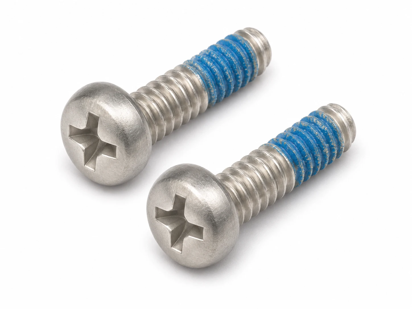
Thread-Locking Pan Head Screws
A raised head with a flat bearing face for surface-mounted joints. Review head clearance and the matching drive together with the thread and treatment location.
Selection focus: head diameter, head height and driver fit.
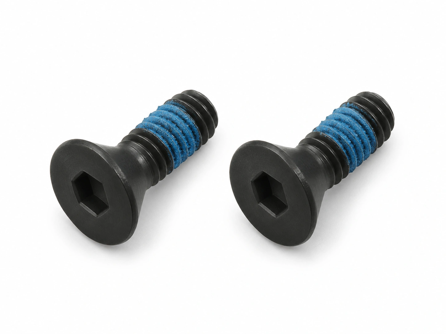
Thread-Locking Countersunk Screws
A tapered bearing face for a matching countersink. Review the head angle, seating depth and remaining panel thickness when the finished surface needs to be flush.
Selection focus: countersink geometry, seating depth and length reference.

Thread-Locking Hex Head Screws
An externally driven head for wrench or socket installation. The illustrated example has a flange; its bearing geometry and tool clearance must fit the surrounding assembly.
Selection focus: width across flats, socket clearance and bearing-face geometry.

Thread-Locking Truss Head Screws
A wide head with a shallow profile and a flat bearing face. Check its coverage of the mounting hole and the space available around the head.
Selection focus: head diameter, projecting height and surrounding clearance.
Specify the Screw and the Treatment Together
The base screw and its locking treatment form one part specification. A nominal diameter and length do not identify the head fit, mating-thread engagement or the location of the active coating.
| Feature | Configuration or selection point | Assembly implication |
|---|---|---|
| Head and drive | Socket cap, button, pan, countersunk, hex or truss head, with a compatible drive | Establishes the bearing interface and tool access |
| Machine thread | Diameter, pitch, tolerance and complete-thread length | Must match the receiving thread |
| Screw length | Length and measurement reference defined for the head style | Controls reach, engagement and blind-hole clearance |
| Shank and thread zones | Full or partial thread and any drawing-defined shank features | Separates clamping, clearance and engagement requirements |
| Treatment identity | Specified coating system and its technical requirements | Determines the applicable installation and performance criteria |
| Coating position | Start position and length relative to a defined drawing reference | Places the treatment within the intended mating-thread engagement |
| Circumferential coverage | Localized or full-circumference treatment, reviewed for the specified system | Defines coverage without assuming a universal locking strength |
| Material | Carbon steel or stainless steel, with the exact grade and condition agreed for the part | Affects manufacturing, finishing and treatment compatibility |
| Surface condition | Specified plating, cleaning, passivation or other applicable finish | Influences adhesion, friction and final thread fit |
| Acceptance requirements | Agreed dimensional, coating and functional checks | Provides a reference for sample and production acceptance |
Countersunk screw length commonly includes the head, while the other head styles shown are normally measured from the underside of the head. The approved drawing and applicable product specification define the final reference.
Place the Treatment Where the Threads Engage

- Coating start
- Coating length
- Coated region
- Lead-in threads
- Mating-thread engagement
- Joint thickness
A treatment zone outside the engaged threads cannot replace contact within the intended mating region. Define coating position against the installed joint, including the clamped stack, receiving-thread location and any clearance at the screw tip.
Carbon steel and stainless steel configurations are reviewed against the complete part requirements. Material grade, finish and treatment are selected together; the options shown do not imply that every combination is suitable.
Resolve the Fit Before Setting the Locking Requirement
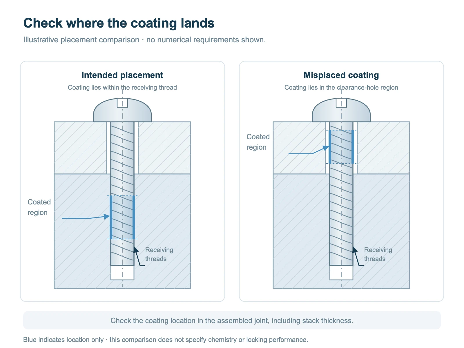
The Coating Misses the Working Thread Zone
A suitable treatment still needs contact with the mating threads. Review the coating start and length against the installed position, rather than judging the part only by how much coating is visible.
Added Running Resistance Changes Installation
A locking treatment can change the torque required to turn the screw before the head seats. The assembly procedure must distinguish this running resistance from the final tightening requirement and the resulting joint preload.
The Finish and Treatment Need to Work Together
Plating, cleaning residues, oil and later processing can affect coating adhesion and thread friction. Review the finished surface and processing sequence before approving the sample.
| Assembly condition | Relevant configuration | Check before selection |
|---|---|---|
| Equipment covers with limited projecting space | Button or shallow-profile head, as the joint permits | Head envelope, tool engagement and planned maintenance |
| Panels requiring a flush surface | Countersunk head | Countersink fit, seating depth and remaining material |
| Mounting points requiring wider hole coverage | Truss or flange-head configuration | Bearing support, head diameter and nearby features |
| Machine assemblies accessed by a socket or wrench | Socket cap or external hex head | Tool approach, receiving thread and treatment engagement |
Coordinate Custom Geometry and Pre-Applied Treatment
Shi Shi Tong reviews the head, drive, thread and treatment zone as one drawing-defined part. This helps align the screw’s mechanical fit with the specified locking requirement.
Pre-applied treatment can move the application step away from final assembly and make the coating location part of the supplied component specification. The selected system still needs the correct installation conditions.
Material and finishing requirements are reviewed before sample approval. The drawing revision, treatment reference and acceptance criteria provide a common basis for production and inspection.
| Drawing Review | Review screw geometry, mating components and the intended treatment zone |
| Process Planning | Select the manufacturing route and coordinate applicable finishing and treatment requirements |
| Sample Evaluation | Assess dimensions, coating placement and agreed functional criteria |
| Production Acceptance | Inspect against the approved drawing and order-specific requirements |

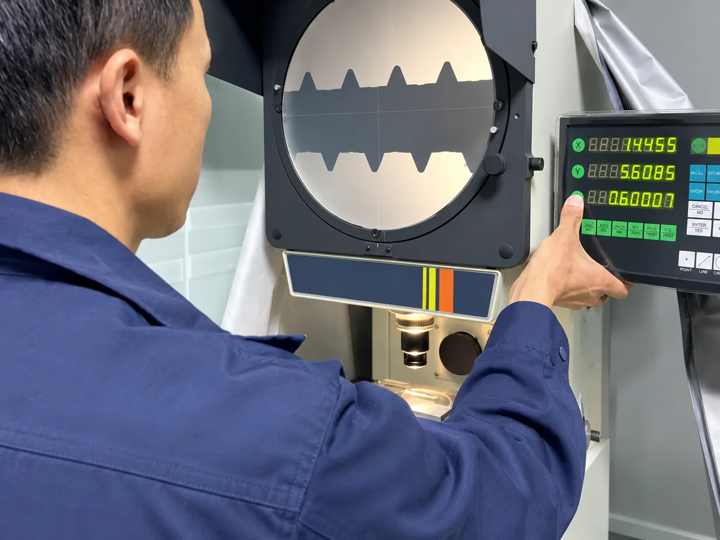
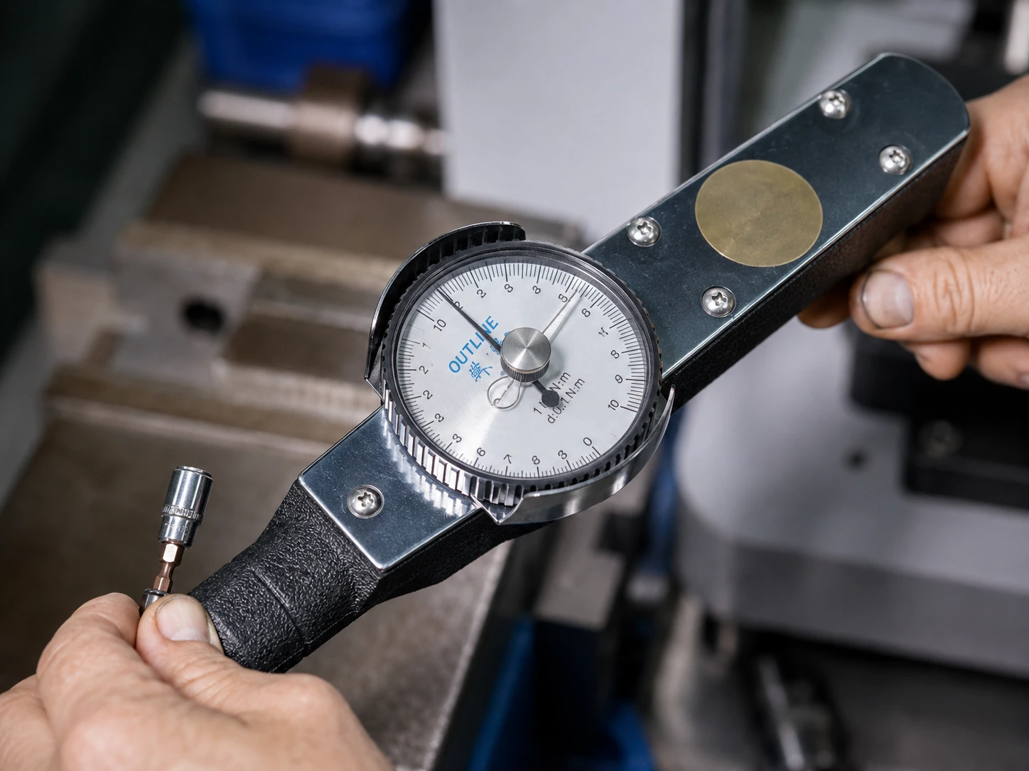
Inspection Planned Around the Finished Part
Dimensional, thread and coating requirements are reviewed together. Functional acceptance is defined for the specified treatment and mating conditions, including the relevant installation and removal measurements where required.
| Inspection area | Project-specific scope |
|---|---|
| Screw geometry | Critical head, drive, shank and length dimensions |
| Thread condition | Thread dimensions, fit and gauge requirements at the appropriate processing stage |
| Treatment placement | Specified coating location, length, coverage and appearance |
| Functional measurements | Agreed running, tightening or removal measurements under defined test conditions |
| Material and finish | Specified material condition, surface requirements and relevant documentation |
| Additional tests | Hardness, corrosion or other applicable testing when included in the order |
Thread Locking Screw Selection Guide
How do pre-applied thread-locking treatments work?
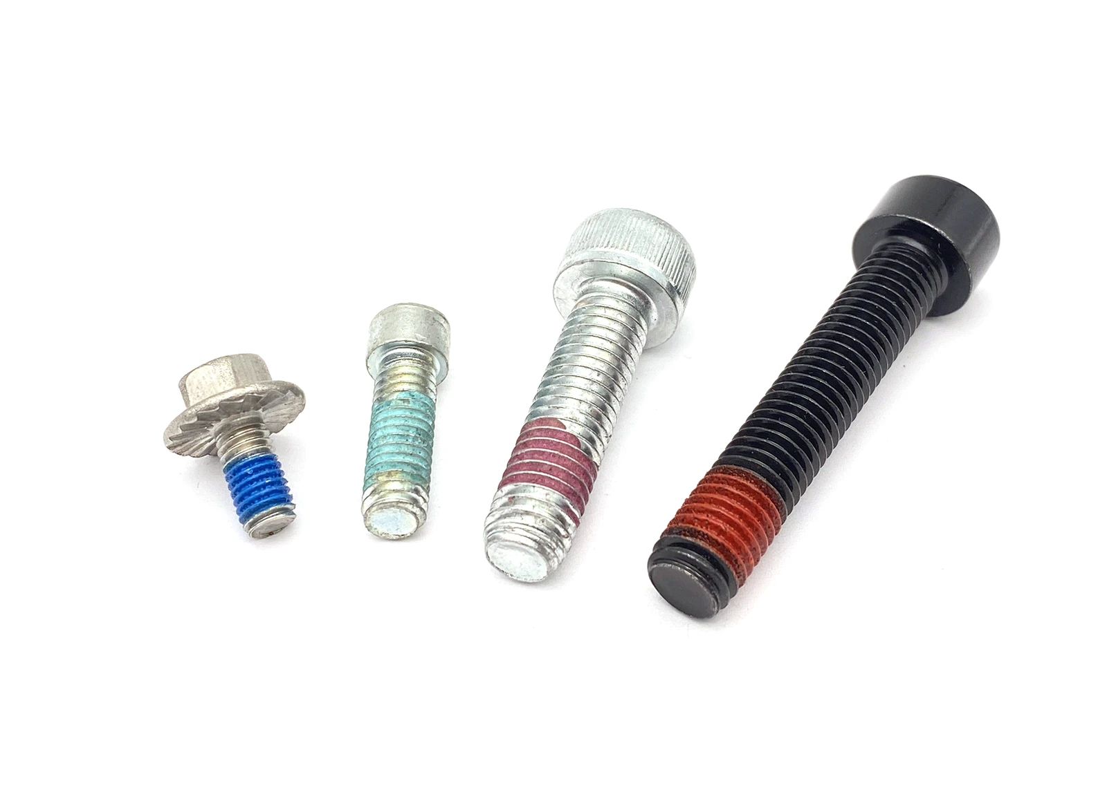
Pre-applied treatments add a locking function at the mating threads. The mechanism depends on the specified system; the colour of the coating does not identify its chemistry or strength.
| Common mechanism | How it works | Selection implication |
|---|---|---|
| Non-reactive polymer patch | The patch is compressed between mating threads and creates additional resistance to rotation | Running torque, fit and any permitted reuse need to be defined |
| Reactive pre-applied coating | Assembly activates the coating, which develops an adhesive bond according to its curing requirements | Cure conditions, removal requirements and service limits need to be specified |
An untreated screw has no added locking treatment. A pre-applied screw arrives with the specified treatment already on the component, while a user-applied liquid threadlocker adds an application step during assembly.
The head style does not identify the locking system. For a custom part, the treatment reference is agreed separately from the head, material and thread dimensions.
Where should the coating be placed on the screw?
Place the specified treatment where it will contact the intended mating threads in the installed joint. Its position needs a drawing reference, not just a description such as “near the tip”.
Review four related dimensions:
- The installed position of the screw after the head seats.
- The start and length of the receiving thread.
- The coating start, coating length and required circumferential coverage.
- Any lead-in, clearance or unthreaded section that affects engagement.
For the six head styles shown, the coating zone is coordinated with the actual screw geometry and joint stack. Full-circumference coverage does not automatically mean greater locking strength or a sealed connection.
Which installation and removal torque values matter?
Running resistance, final tightening torque and removal measurements describe different stages of assembly. They should be specified and measured separately.
| Measurement | Meaning |
|---|---|
| Running torque before seating | Resistance while the screw turns through the engaged treatment before the head clamps the joint |
| Final tightening torque | The applied torque used to complete tightening under the defined assembly procedure |
| Initial breakaway torque | The torque required to start loosening under the stated test condition |
| Continued removal torque | Resistance measured after initial loosening as the screw continues to turn out |
Test conditions must identify the mating thread, surface condition, temperature, speed and whether joint preload is present. Reactive systems also require a defined cure condition before the relevant measurements.
Do not transfer an untreated screw’s tightening setting directly to a treated part without evaluating the changed friction and running resistance. A locking torque result alone does not establish the joint’s clamp load.
Can the screws be reused, and what controls curing and temperature limits?
These limits belong to the specified treatment system and its validated assembly conditions.
A non-reactive friction patch can act during installation. Whether it permits adjustment or repeated use depends on the system, thread fit and acceptance criteria. A reactive coating may require defined curing conditions, and removal does not automatically permit reuse without renewed treatment.
Temperature must be assessed at the threaded joint, including continuous exposure, short peaks and thermal cycling. Cleaning agents, fluids, finishes and storage conditions may also affect the treatment.
Agree the maintenance procedure and the required performance after any permitted assembly cycle. Use the selected system’s technical data and project validation rather than a universal reuse count, curing time or temperature rating.
Which standards and records should I request?
Separate the base screw requirements from the locking-treatment specification and the final joint validation.
| Requirement | What it establishes |
|---|---|
| Screw drawing and applicable product standard | Head, drive, thread, dimensions, material and relevant mechanical requirements |
| Locking-treatment specification | The identified system, coating location, processing and functional acceptance requirements |
| Agreed test method | Mating parts, test conditions, measurement sequence and acceptance criteria |
| Part and batch records | The drawing revision, material and processing references associated with the supplied parts |
DIN 267-27:2024-07 addresses microencapsulated adhesive coatings. DIN 267-28:2026-02 addresses locking coatings that produce a clamping effect. Their applicability depends on the defined product and coating system.
For procurement, compare quotations against the same drawing, treatment reference and test requirements. Shi Shi Tong reviews inspection and documentation needs for each custom order.
Resistance to vibration loosening must be evaluated for the actual joint and relevant test conditions. A quality-system certificate or coating name does not replace that evaluation.
For a joint that also needs a sealing interface, explore custom sealing screws.
For restricted tool access, review custom security screws. Security-drive geometry and thread locking address different requirements.
Request a Custom Thread Locking Screw Review
Share your drawing or sample reference to review the screw geometry and pre-applied treatment together. Include the quantity, material, finish, mating-thread details and any specified installation or removal requirements.
If a treatment system has already been selected, include its reference and the applicable acceptance criteria.
+86 131 4344 4311