Truss Head Machine Screws from a Custom Manufacturer
A broad, low-domed head for joints where the head sits above the mating surface. Shi Shi Tong develops and manufactures drawing-based machine screws, with head clearance, drive geometry, thread engagement and finish reviewed as one configuration.
Made to drawing in Shenzhen, China.
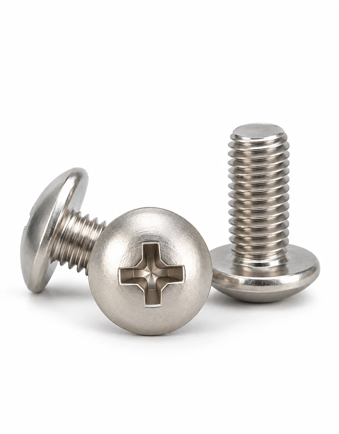
A Wide, Rounded Head with Machine Threads
A truss head provides a broad, shallow head profile with a non-countersunk bearing surface. A machine screw connects to a compatible nut, tapped hole or specified threaded insert. Head shape and thread type describe different features of the same part.
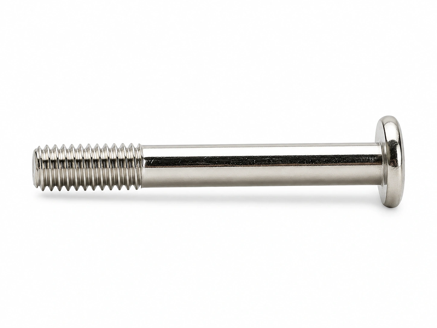
The configuration examples include a cross recess with a long plain shank and a defined threaded end, and a slotted head with full thread. They illustrate different drive and thread-coverage requirements within a drawing-based product.
A flanged or modified head needs its own defined geometry. It should not be assumed from the term "truss head."
| Product feature | Configuration basis |
|---|---|
| Head form | Ordinary broad, low-domed truss head with a non-countersunk seat. |
| Connection | Machine thread matched to the specified nut, tapped hole or threaded insert. |
| Drive examples | Cross-recess and slotted configurations; the exact recess geometry and driver size follow the approved drawing. |
| Thread coverage examples | Full thread, or a plain shank with a defined threaded end. |
| Main dimensions | Thread designation, under-head length, threaded length, head diameter and head height. |
| Material and finish | Exact grade, condition and finish reviewed for the individual geometry and service requirements. |
| Supply basis | Drawing review, manufacturing-route selection and project-specific sample and inspection requirements. |

Truss Head, Pan Head or Countersunk Head?
For comparable screw sizes, a truss head generally offers a wider, shallower profile than a pan head. The actual drawing determines the dimensions. Both sit above the surface; a countersunk head uses a different seating arrangement.
A wider head does not by itself establish a higher load rating or greater installation torque. A head-style change also needs to preserve the specified connection and tool access.
| Head profile | Main selection reason | What to check |
|---|---|---|
| Truss head | A broad head envelope where installed height and bearing coverage matter. | Available width, supported seating area, head height and drive-recess geometry. |
| Pan head | A different balance of head diameter, height and drive envelope where a narrower head may fit. | The actual head and recess dimensions; the thread size alone does not establish interchangeability. |
| Countersunk head | Flush or recessed seating when the joint includes the specified countersink. | Countersink angle and depth, remaining material and the required seating condition. |
Make Head Coverage, Clearance and Engagement Work Together
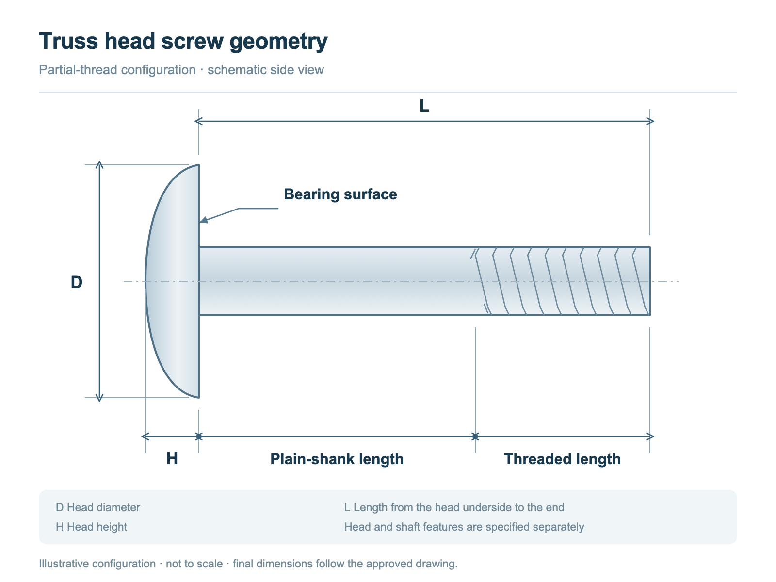
Key Configuration Dimensions
- Head diameter
- Head height
- Under-head length
- Plain-shank length
- Threaded length
- Mating thread
For this non-countersunk head, length is measured from the underside of the head to the end of the screw. Threaded length and head height are separate dimensions.
Covering the hole is only part of the fit
A broad head can overlap a hole or slot while still having too little support beneath it. The local panel shape, material thickness and bearing seat determine how contact is established. We review the head diameter with the mating geometry rather than treating overlap alone as a load or pull-through rating.
A plain shank changes where the thread can engage
A partially threaded screw can pass through a clearance section before its thread reaches the mating feature. The plain-shank length, threaded length and joint stack need to work together. A screw that reaches the bottom of a blind hole before seating will not provide the intended clamping condition.
A low head still needs a usable drive
Head height, recess depth, remaining material and driver access are linked. We review the actual drive geometry with the head profile and finished condition, including any coating allowance, so the selected tool can engage the specified recess.
| Assembly situation | Useful design check | Connection implication |
|---|---|---|
| Equipment covers and thin panels | Supported head contact, hole or slot dimensions and the permitted effect on the surface. | A compatible nut, insert or tapped feature is needed for the machine thread. |
| Brackets and housings with limited head space | Head diameter, installed height and the complete tool-access path. | The wide profile must clear adjacent parts while the driver reaches the recess. |
| A joint with a long clearance section | Position of the plain shank and the start of the threaded section. | The specified thread must reach and engage the mating feature without interference or bottoming. |
Custom Engineering for a Broad, Shallow Head
Head profile and drive reviewed as one geometry
Increasing head diameter or reducing head height changes more than appearance. It affects material flow during forming, the section around the recess and the space available for the driver. Shi Shi Tong reviews the head, recess, head-to-shank transition and assembly clearance together before the manufacturing plan is defined.
A manufacturing route matched to the requirement
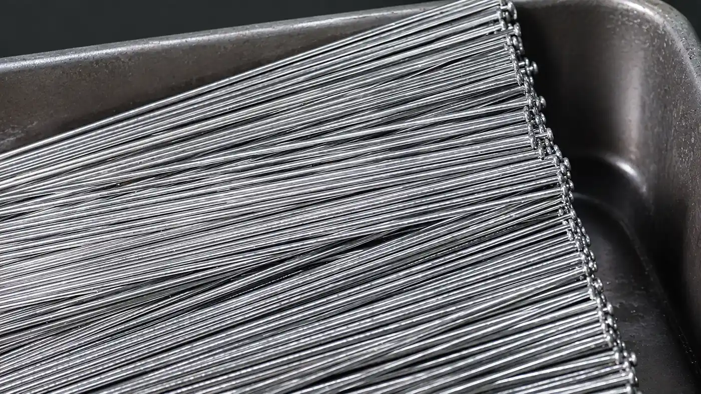
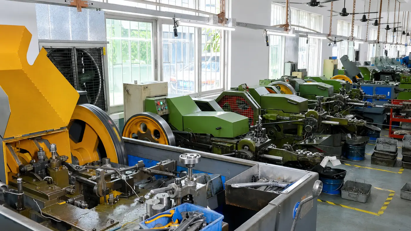
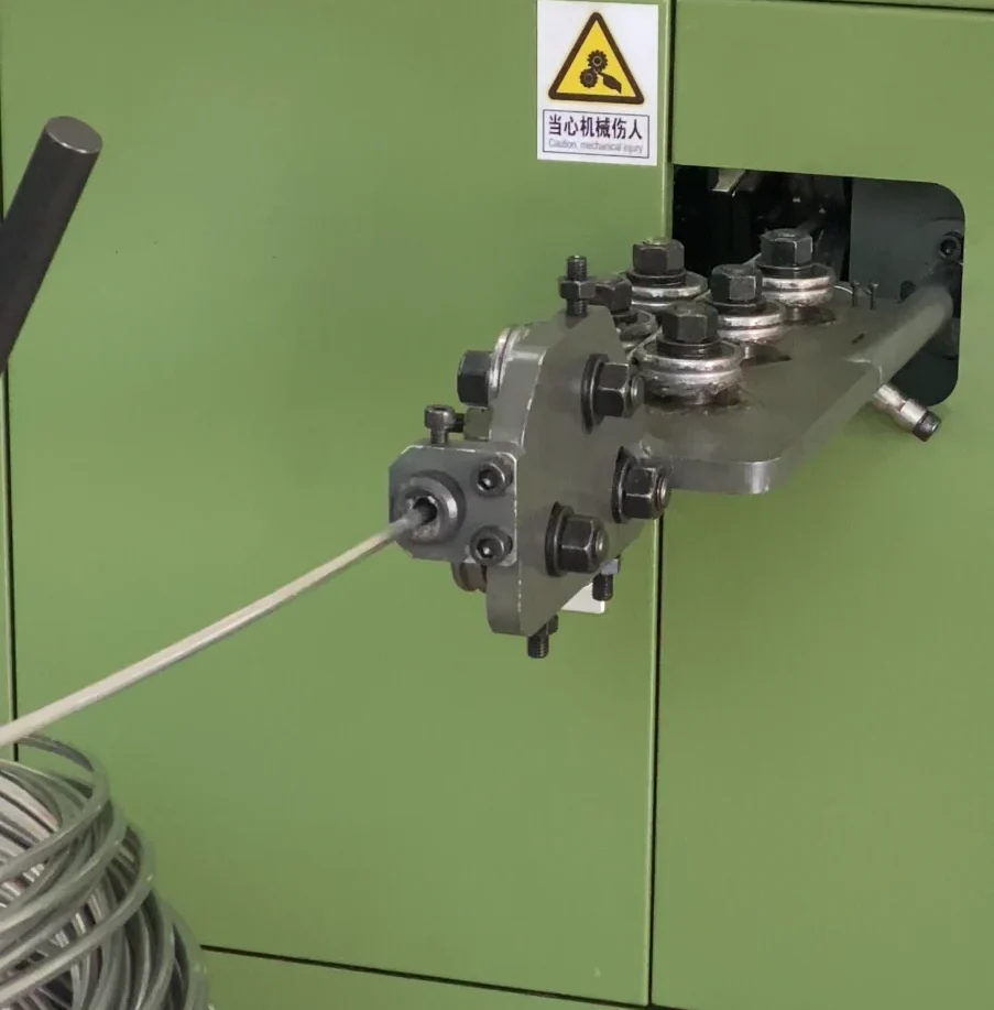
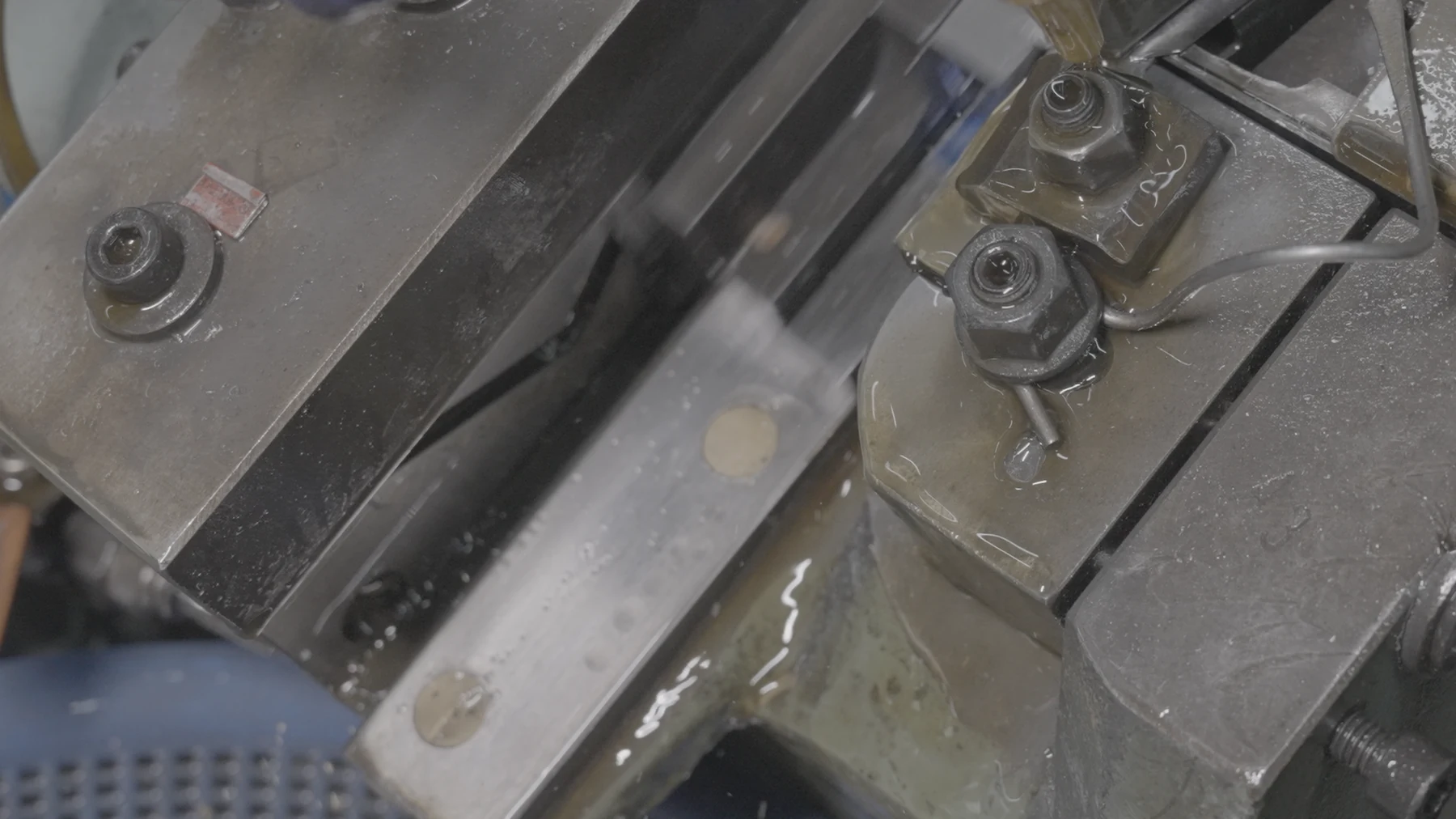
Cold heading and precision machining offer different ways to achieve a custom screw geometry. Material, proportions, quantity and acceptance requirements determine the route. Tooling development, secondary machining and sample validation are planned where the actual part requires them.
Drawing Review, Sample Validation and Inspection
Shi Shi Tong has been manufacturing screws since 1998. Manufacturing in Shenzhen is supported by drawing review, process planning, tooling and sample validation according to the requirements of the individual part.
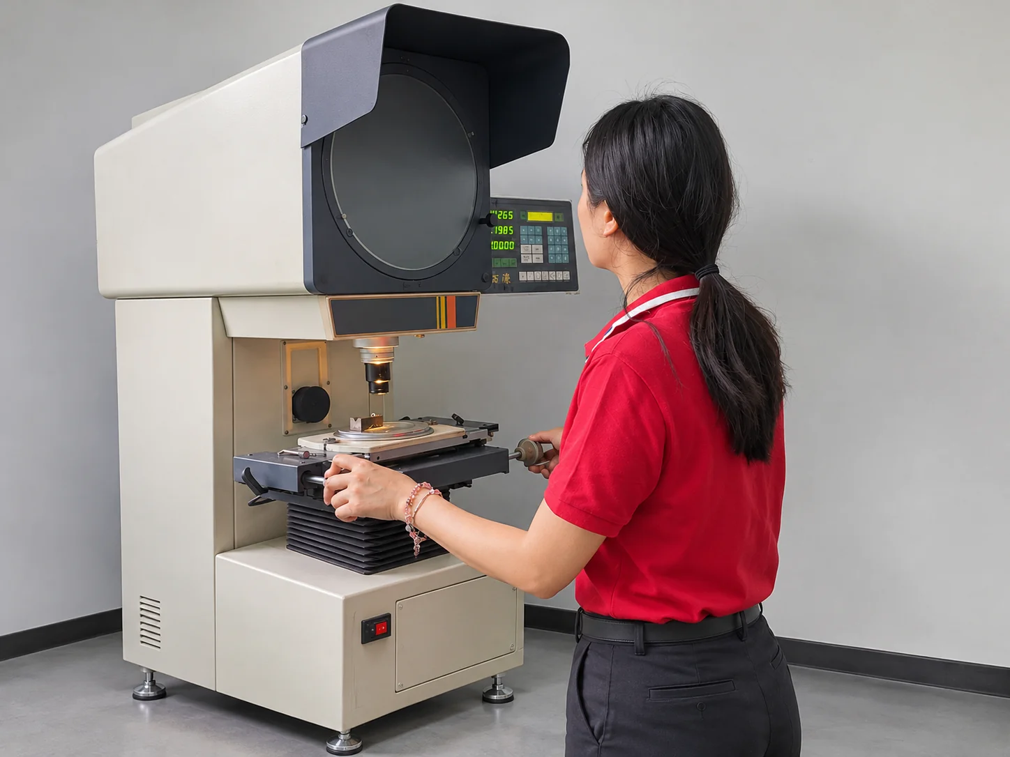
For a truss head machine screw, inspection planning can cover head diameter and height, recess geometry, under-head length, thread coverage and the final thread fit. Optical profile inspection and thread gauging are selected where appropriate; material, hardness, torque or surface testing is defined by the project requirements.
Keep the approved configuration consistent
The drawing revision, material condition, finish and acceptance requirements provide the reference for sample approval and subsequent production. Changes to the drive, threaded section or coating need to be reviewed against that reference.

Truss Head Machine Screw Buying Guide
Use these checks to complete the thread, material and purchasing specification after selecting the head envelope and assembly fit.
Guide Topics
Can a machine screw fasten a thin sheet without a tapped hole?
It can be part of that assembly when a compatible nut, threaded insert or another specified threaded feature provides the engagement. An ordinary machine screw is not selected to cut its own thread in plain sheet simply because it has a truss head.
The available thread engagement and the seating area beneath the head are separate checks. A wide head may help cover a clearance hole, but the joint still needs the intended threaded connection. The partial-thread configuration must also place its plain shank and threaded end correctly within the stack.

These distinct sections must align with the joint stack to clamp effectively.
How do metric and inch size designations differ?
A complete designation identifies the thread system as well as its diameter and pitch. Metric threads use dimensions in millimetres; Unified inch threads use a numbered or fractional diameter and threads per inch. Similar appearance or nominal diameter is not enough to establish a match.
| Thread system | Identification to retain | Additional drawing requirements |
|---|---|---|
| Metric | M designation, nominal diameter and pitch. | Thread tolerance where specified, under-head length, head dimensions and drive geometry. |
| Unified inch | Numbered or fractional diameter, threads per inch and the specified series. | Thread class where specified, under-head length, head dimensions and drive geometry. |
The drive style and bit size are separate from the thread designation. The cross-recess and slotted examples on this page therefore need their own recess requirements. Confirm them on the finished-part drawing rather than selecting a bit from the thread diameter alone.
Which materials and finishes should I consider?
Carbon steel, alloy steel and stainless steel are common material directions for machine screws, but the exact grade and condition need to suit the geometry, required mechanical properties and service environment.
For stainless grades such as 304 or 316L, consider the exposure conditions and the metals in contact with the screw. Stainless steel is not suitable for every corrosive environment. For carbon or alloy steel, the protective finish and its acceptance requirements are part of the specification where corrosion protection is needed.
Head and drive proportions also affect the manufacturing review. A finish can change thread fit and recess clearance, so the required condition after processing matters. Specify the material grade and finish explicitly; color alone does not establish a coating system or corrosion rating.
What should I compare in a bulk-order quotation?
Use the same drawing revision and finished-part requirements for each quotation. Head and recess dimensions, thread coverage, material condition and inspection scope can change the manufacturing requirement even when two parts share the same thread size.
Compare:
- Head diameter and height, drive type and actual driver size.
- Thread designation, under-head length, plain-shank length and threaded length.
- Material grade, required properties and finish.
- Sample and tooling arrangements, order quantity and repeat-order basis.
- Inspection, documentation, packaging and delivery terms included in the quotation.
Shi Shi Tong reviews the configuration before defining the manufacturing route and quotation. Sample quantities, production minimums, tooling charges and lead time are confirmed for the individual project.
Discuss Your Truss Head Machine Screw Drawing
Share the head diameter and height, thread designation, length, thread coverage, material, finish and estimated quantity. A drawing or mating-part detail helps us review the head envelope, drive access and connection requirements together.
Our team will review the configuration, manufacturing route and sample or inspection requirements for your project.