
Custom Machine Screws Manufacturer
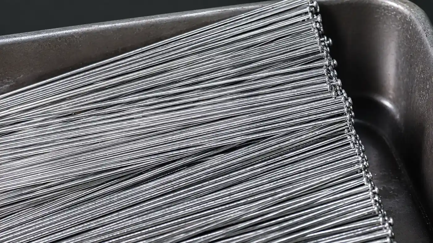
Shi Shi Tong manufactures custom machine screws around your drawing and assembly requirements. Compare ten head styles, then define the thread, material, length and functional details that make the screw fit your connection.
- Head and drive geometry reviewed together
- Drawing-defined threads, shanks and lengths
- Material, finish and inspection matched to the part
Choose the Head Style for Your Assembly
Machine screws engage a matching tapped hole, threaded insert or nut. The head determines how the screw seats and how much installation space it needs. Drive type, thread, material and length are separate choices that must work with that head geometry.
The configurations below are starting points for custom manufacture. Final dimensions and manufacturing feasibility are reviewed against the drawing.
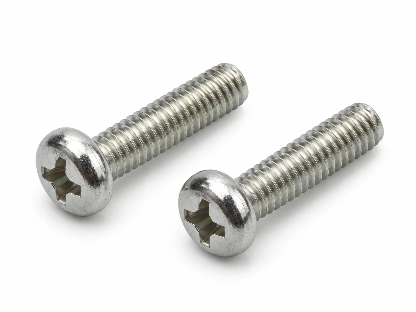
Pan Head Machine Screws
A raised head with a flat bearing surface for assemblies where the head remains above the component. Compare head diameter, height and driver access.

Flat Head Machine Screws
A conical seating surface for installation in a matching countersink. Head diameter, countersink angle and the length reference determine how the screw seats.
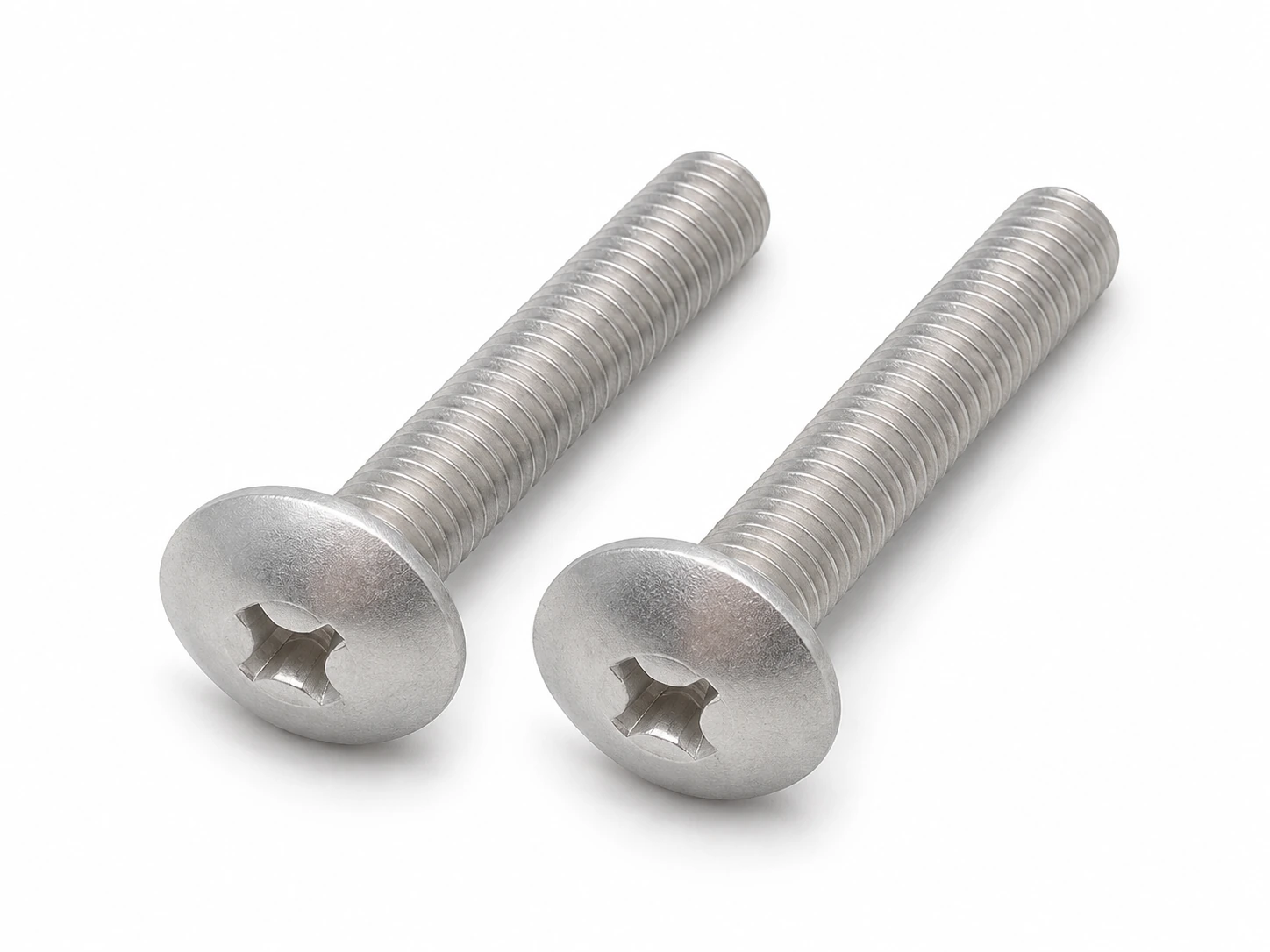
Truss Head Machine Screws
A broad, shallow head provides a larger seating footprint. Compare the supported bearing area, hole coverage and available head clearance.

Button Head Machine Screws
A rounded head profile with a bearing face beneath the head. Match head height, socket dimensions and tool access to the available installation space.

Socket Head Cap Screws
A cylindrical head and internal hex drive provide a distinct head envelope. Check head height, counterbore clearance and usable socket depth together.
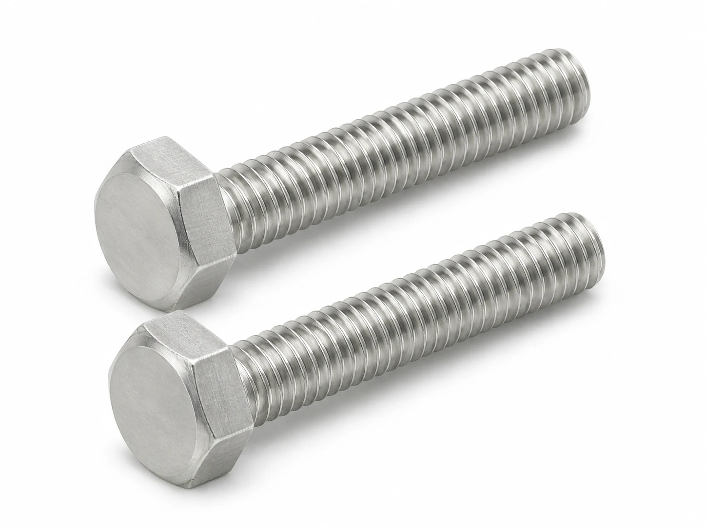
Hex Head Machine Screws
External flats provide wrench or socket engagement. Across-flats dimensions, head height and the tool’s approach path are important selection details.
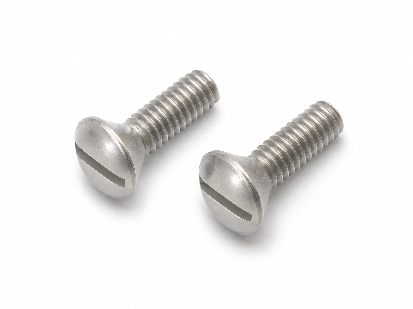
Oval Head Machine Screws
A raised, rounded top sits above a conical seating surface. Choose this profile when the assembly requires a countersunk seat with a visible domed head.

Cheese Head Machine Screws
A flat top and straight cylindrical sides distinguish this profile from a domed pan head. Compare head diameter, height and slot dimensions.
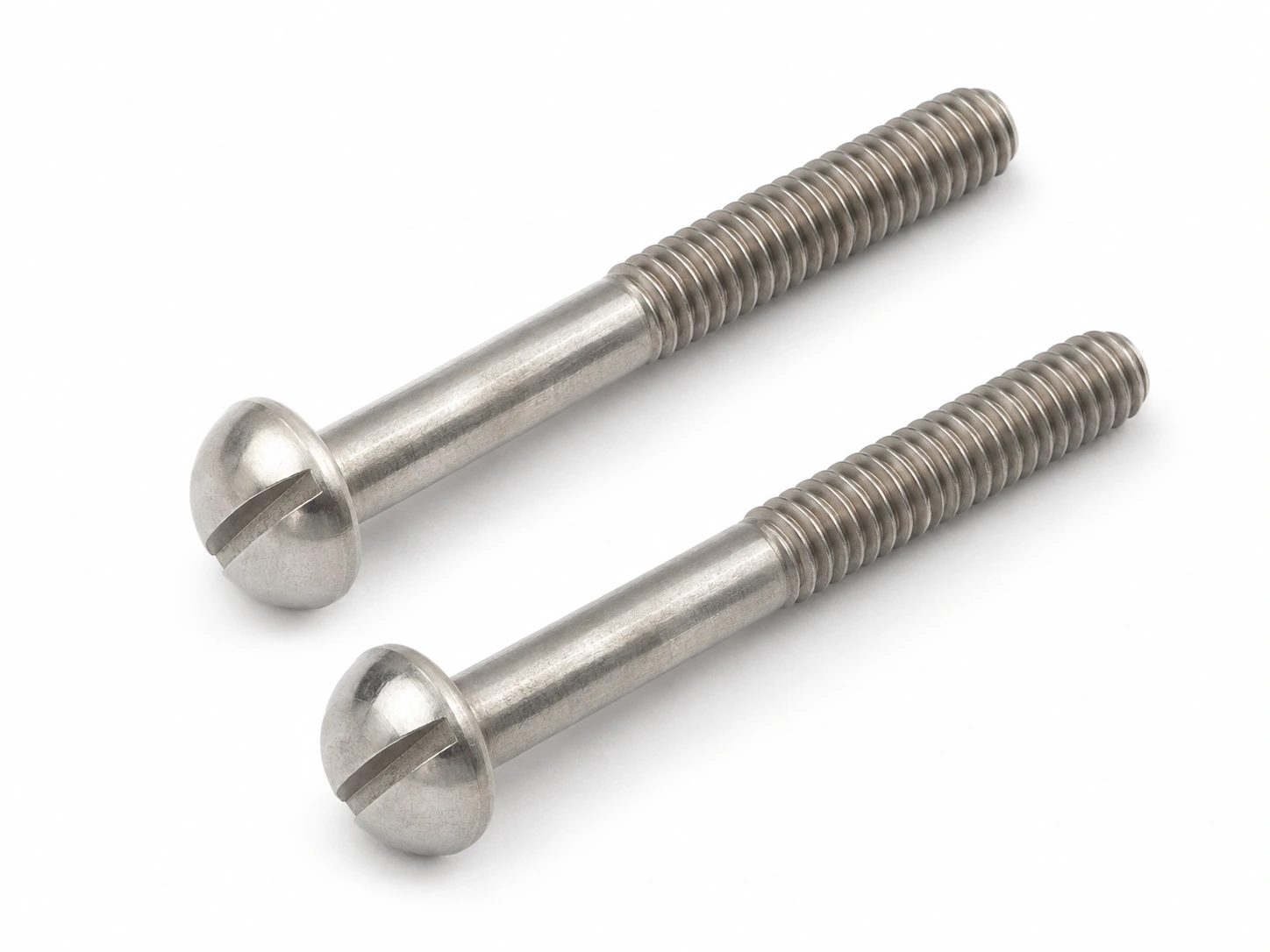
Round Head Machine Screws
A pronounced rounded dome creates a different external profile from pan and button heads. Check head projection, seating area and any required plain-shank length.
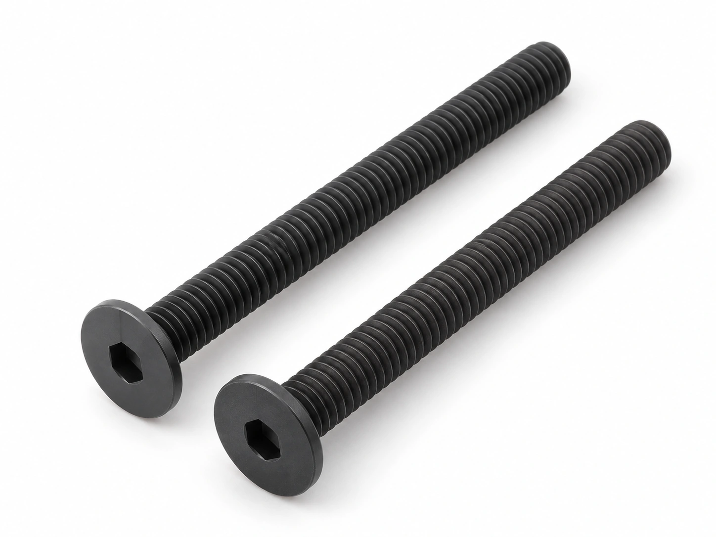
Low-Profile Machine Screws
Thin head forms suit restricted vertical space. Head thickness, bearing area, drive depth and the remaining head section must be considered together.
Specify the Features That Control Fit
A nominal diameter and length identify only part of the screw. The head, thread, seating surface and usable engagement must match the receiving component. Custom dimensions are evaluated as a complete design.
| Feature | Available design direction | Selection priority |
|---|---|---|
| Head and seating surface | Ten head-style directions with drawing-defined dimensions | Head diameter, height, bearing face and countersink or counterbore fit |
| Drive | Phillips, slotted, hex socket, six-lobe and reviewed combination or special drives | Correct tool fit, recess depth and installation access |
| Thread | Metric or inch machine threads reviewed to the specification | Diameter, pitch or TPI, fit and mating thread |
| Length and threaded zone | Full thread, partial thread or drawing-defined plain shanks | Length datum, useful engagement and clearance |
| Functional geometry | Shoulders, grooves, retaining features or drilled passages | Relationship to the mating components and remaining material |
| Finished condition | Material-specific surface treatment and agreed inspection | Coating build-up, thread fit and functional dimensions |
Custom head, drive, material and functional features are assessed together. A configuration shown in one material does not establish every possible combination.
Choose Material for the Joint and Environment
| Material direction | When to evaluate it | What affects the final choice |
|---|---|---|
| Carbon and alloy steel | Projects with defined mechanical-property and cost requirements | Grade, condition, heat treatment, finish and finished-part properties |
| Stainless steel, including 304 and 316 directions | Assemblies where corrosion exposure and material compatibility matter | Exact grade, exposure, surface condition and mating material |
| Brass and copper | Designs with specified copper-alloy, appearance or electrical requirements | Exact alloy, mechanical properties, surface treatment and required validation |
| Titanium | Designs with defined mass, corrosion or material requirements | Grade, condition, geometry, manufacturing route and mating conditions |
| Aluminum | Designs prioritizing lower fastener mass or a specified anodized appearance | Alloy, temper, thread strength and finish; supplied through turning or machining |
Material names do not establish a finished screw’s strength, corrosion life or installation torque. Grade, condition, geometry and acceptance requirements belong in the same specification.
Match the Screw to the Assembly
| Assembly context | Selection focus |
|---|---|
| Electronics and compact housings | Head envelope, tool access, mating thread and clearance from internal components |
| Equipment joints and brackets | Seating area, clamp stack, usable engagement and the specified mechanical properties |
| Removable covers and service panels | Access during servicing, release travel and any separately required retention or sealing feature |
Illustrative joint geometry. Final dimensions follow the assembly drawing.
Resolve the Details That Affect Assembly
The Head Fits, but the Tool Cannot Reach It
A head can clear the component while leaving too little room for the driver or socket. We review head dimensions, recess geometry and the installation path together before selecting the manufacturing route.
The Screw Reaches the Hole but Does Not Clamp
An incorrect plain-shank position, insufficient usable thread or contact with the bottom of a blind hole can prevent the intended joint from seating. Length references, thread zones and receiving-hole geometry are considered together during drawing and sample review.
The Finished Part Fits Differently
Heat treatment and surface finishing can affect dimensions, friction and thread fit. Material condition, thread requirements and finish are reviewed together, with checks defined for the finished part.
Custom Geometry with a Defined Production Route
Our head-style and functional-feature range provides starting points when a standard screw does not match the assembly. We review linked features on one drawing so the head, shank, thread and finish follow the same specification.
The manufacturing route follows the actual part. Depending on material, geometry and quantity, it may involve cold heading, multi-station forming, turning, thread production or necessary secondary machining. Sample review and agreed inspection criteria connect that route to the approved design.
Add the Function Your Connection Needs
Head style is one part of the design. These related directions address washer handling, location, retention, locking, access or passage requirements. Features may overlap, with each combination reviewed against the assembly.
Flange Head Screws
An integral flange provides an enlarged bearing face in selected hex, button and truss configurations.
SEMS Screws
Preassembled washers remain with the screw for handling and installation.
Shoulder Screws
A controlled shoulder or stepped section provides a locating, spacing or moving interface.
Captive Screws
Screw geometry works with a retaining interface to keep the loosened screw with the panel.
Thread Locking Screws
Pre-applied thread treatments are selected around the required locking behavior and installation conditions.
Sealing Screws
Sealing features are evaluated with the seating surface and complete sealing interface.
Security Screws
Special drive configurations restrict removal with ordinary tools.
Knurled Thumb Screws
Knurled gripping surfaces support manual operation where access and tightening requirements permit.
Vented Screws
Connected passages provide a route from a trapped volume to an exposed outlet.
Hollow Screws
Headed through-hole designs are reviewed around the required opening and remaining wall section.
Manufacturing and Inspection in Shenzhen
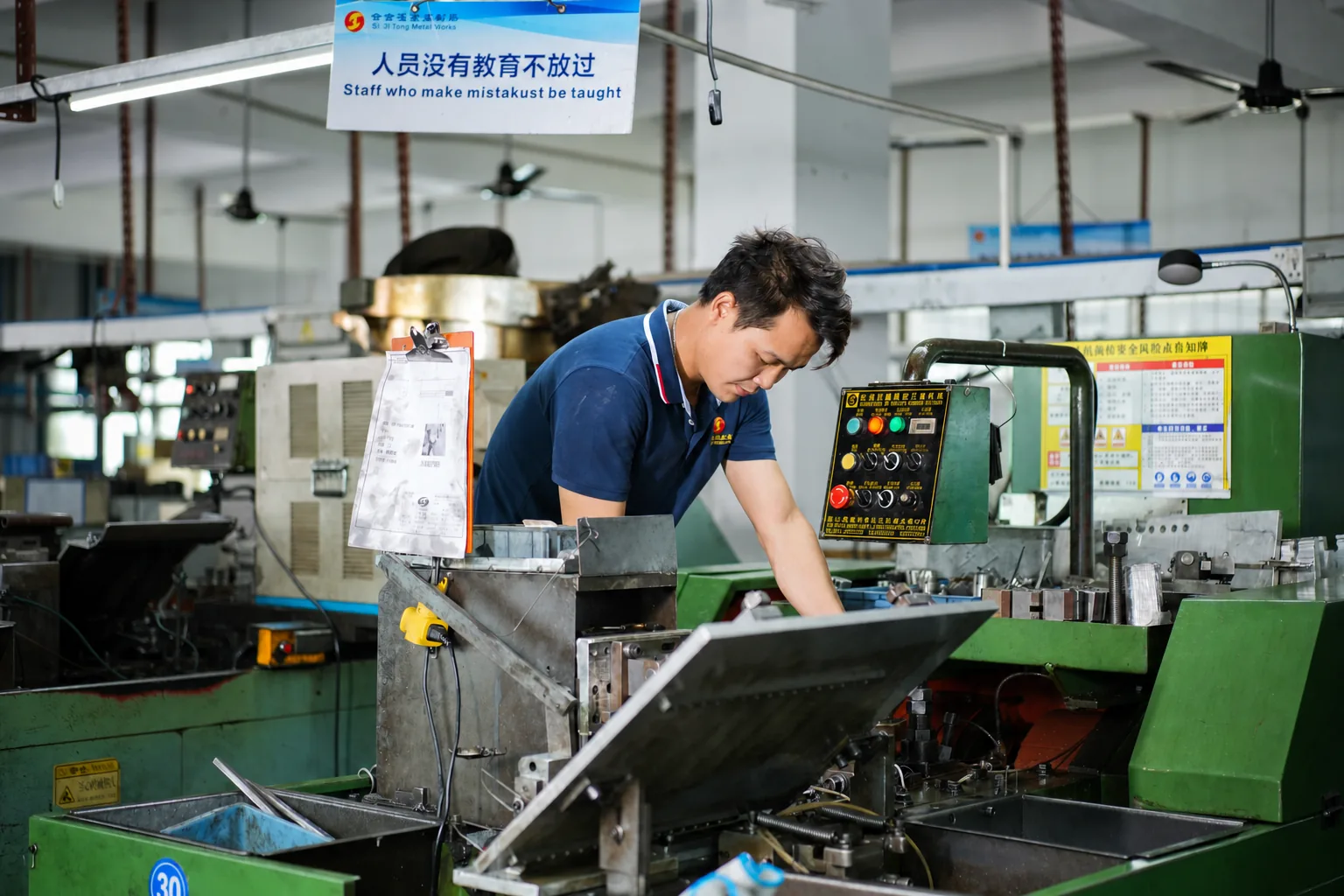
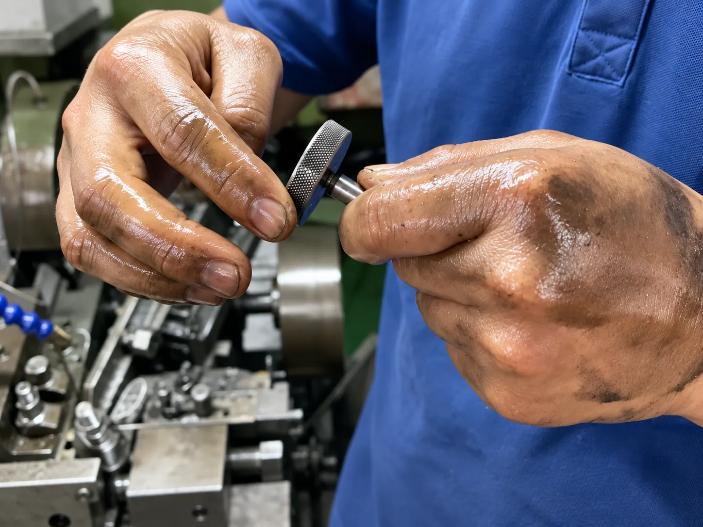
Shi Shi Tong brings screw-manufacturing experience dating to 1998 to made-to-drawing fastener projects. Drawing review, tooling and sample verification, manufacturing planning and batch inspection are organized around the agreed part specification.
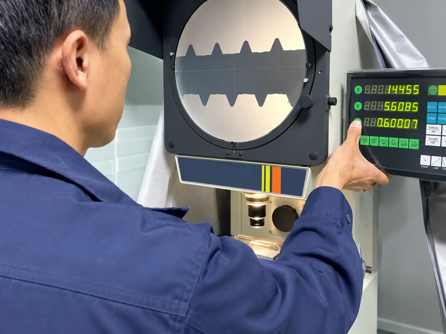
Inspection focuses on the features that control the connection. Depending on the project, this may include dimensional measurement, thread gauging, optical profile checks and specified hardness, torque or corrosion testing.
The applicable checks, methods and records are agreed for the part. Requirements for material documentation or third-party testing are defined with the quotation and inspection plan.
Machine Screw Selection Guide
How do I read a machine screw size and measure it correctly?
A metric designation identifies thread diameter, pitch and length in millimetres. For example, M3 × 0.5 × 12 describes a nominal 3 mm thread diameter, 0.5 mm pitch and 12 mm specified length. An inch designation uses a numbered or fractional diameter, threads per inch and length; a numbered size is not a millimetre diameter.
Measure diameter across the outside of the threads, rather than across the head. Raised-head screws are normally measured from the under-head bearing surface to the end. Flat countersunk screws are normally measured over the head. Oval heads and special geometries require the seating reference shown on the controlling drawing.

How do I choose length for a tapped hole or clearance-hole joint?
Choose length from the complete joint: the clamped stack, any washers, the receiving thread and the usable engagement. A clearance hole allows the screw to pass through; fastening comes from the nut, insert or tapped component beyond it.
For a blind tapped hole, distinguish drilled depth from usable full-thread depth and leave the required bottom clearance. A screw that bottoms before the head seats can feel tight without producing the intended clamp.
Required engagement depends on thread geometry, the strength of both mating materials and the joint load. There is no single engagement multiplier for every material. For a custom partial-thread or long-shank design, the position of the threaded zone is part of the specification.
What should I check for electronics assembly?
Start with the receiving thread and the space around the connection. Alongside diameter, pitch and length, check head diameter, head height, driver access and engagement in the tapped feature or insert.
The screw end must also clear boards, components and moving parts. On short screws, under-head thread runout and the transition to any plain section can affect seating and usable engagement.
Shi Shi Tong’s pan, countersunk, button and low-profile directions provide different head envelopes for review. Drawings should identify critical dimensions and inspection requirements. Electrical insulation, grounding or cleanliness requirements need their own specification and validation.
What determines suitability for outdoor use?
Outdoor suitability depends on the exposure: rain, retained moisture, chlorides, temperature, cleaning and contact with other materials. The environment should be evaluated together with the material grade, surface condition and joint design.
316 stainless steel can be a candidate where chloride exposure matters, but it is not immune to corrosion in seawater or moisture-trapping crevices. Coated steel also requires a defined coating system and acceptance requirement.
Use the material comparison above as a starting point. The exact grade, finish and any corrosion test are agreed for the project; a salt-spray result alone does not establish outdoor service life.
Can screws of the same diameter use the same tightening torque?
A common diameter does not establish a common tightening torque. Thread pitch, material or property class, head and bearing geometry, receiving-thread strength, coating and lubrication all affect the relationship between tightening torque and clamp load.
Drive style affects how the tool transmits torque, but does not independently determine the allowable torque or strength of the connection. Greater length also does not automatically make a screw stronger.
Use the tightening requirement and validation method for the actual joint. For an automotive replacement, follow the original assembly specification rather than selecting by brand reputation or nominal diameter alone.
What is needed for a bulk or custom quotation?
Start with the drawing or applicable specification and its revision. Include the following information so suppliers can quote the same part:
- Head and drive geometry
- Thread system, diameter, pitch or TPI, and fit
- Length reference, threaded length and any plain shank
- Material grade, condition and required mechanical properties
- Finish, critical tolerances and inspection documents
- Trial, batch or annual quantities
- Packaging requirements and delivery destination
Compare tooling or development charges, sample scope, unit price, inspection documents, packaging and freight on the same basis. A retail starting price for a different material, size or pack quantity is not a direct comparison.
Shi Shi Tong reviews custom dimensions and batch requirements against the design and manufacturing route. Samples, minimum quantities and lead time are confirmed for the specific project.
Request a Custom Machine Screw Quote
Share your drawing or describe the machine screw you need. Include the head style, thread, material, length and quantity, together with the dimensions or assembly conditions that matter most.