Flange Head Screws from a Custom Fastener Manufacturer
Shi Shi Tong develops and manufactures drawing-based flange head screws for equipment assemblies. Explore hex, button and truss head profiles, with the flange, drive, thread, material and finish reviewed together for the connection.
Manufactured in Shenzhen, China. Developed around your drawing and assembly requirements.
Three Flange Head Profiles for Custom Manufacture
Definition: A flange head screw has an integral collar beneath the head that provides a wider bearing surface. The flange is part of the screw, rather than a separately fitted washer.
Start with the head profile that fits your assembly. Final head and flange dimensions, drive geometry, thread, material and finish are reviewed together against the drawing.
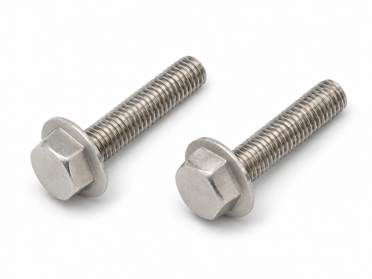
Hex Flange Head Screws
An external hex drive with an integral flange. The external drive suits assemblies with wrench or socket access, while the flange defines the contact area beneath the head. Serrated flange geometry can be reviewed where the mating surface and joint specification permit it.
Selection focus: Compare wrench clearance, flange diameter and bearing-face requirements.

Flanged Button Head Screws
A rounded head with an integral flange. This profile provides a different installed head envelope from an external hex design. Head height and the specified drive geometry need to work within the available tool space.
Compare installed head height, flange diameter and drive access.

Flanged Truss Head Screws
A broad head profile with an integral flange. This is a starting point where head diameter and bearing coverage are important, with the final profile developed around the mating surface and surrounding components.
Compare head diameter, bearing coverage and installation clearance.
Size the Whole Connection, Not Just the Thread
Two screws with the same thread and length can have different flange diameters, head heights and seating conditions. These features determine whether the screw clears adjacent parts, seats correctly and engages the mating thread as intended.
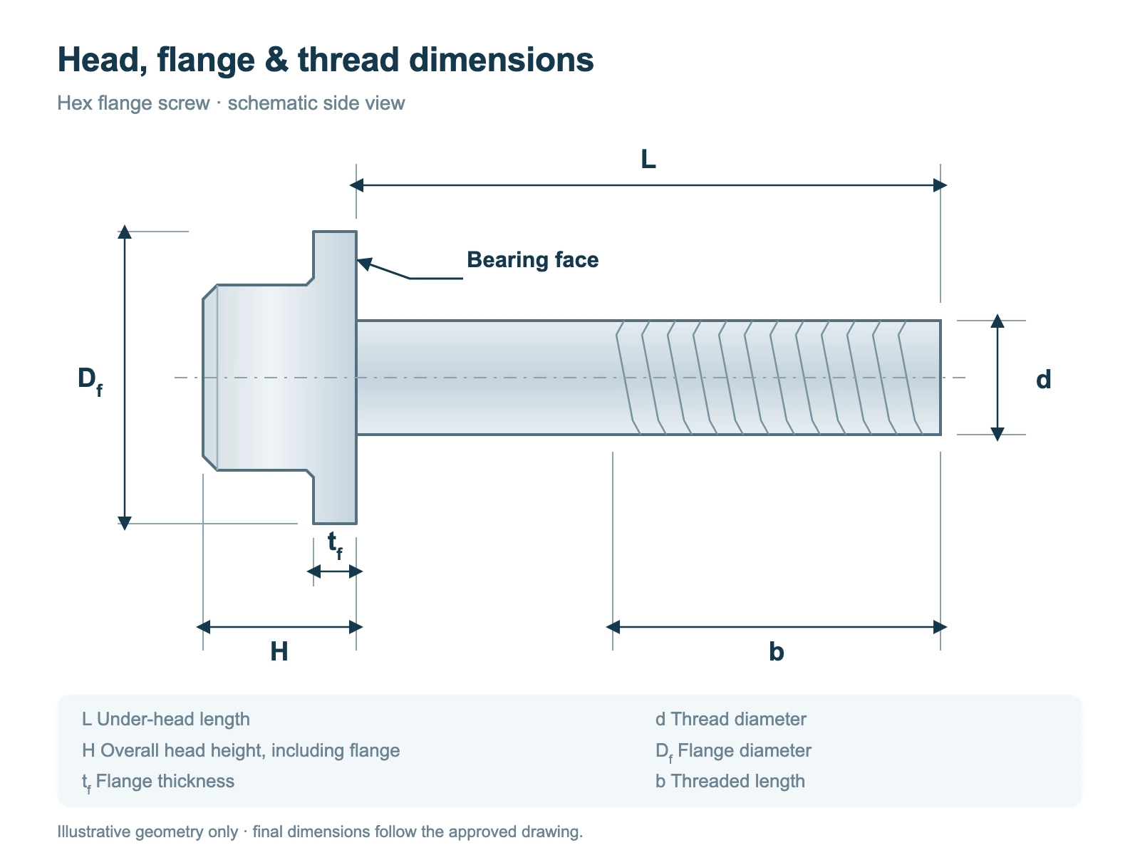
Key Dimensional Features
- Head height
- Flange diameter
- Flange thickness
- Under-head length
- Threaded length
- Bearing surface
| Feature | What it affects | Selection guidance |
|---|---|---|
| Thread diameter, pitch and system | Compatibility with the nut or tapped hole | Match the complete thread designation. Similar-looking metric and inch threads are not interchangeable. |
| Under-head length and thread coverage | Clamped thickness, engagement and blind-hole clearance | Select the length for the stack thickness and required engagement, with allowance for the actual hole depth. |
| Flange diameter and thickness | Bearing coverage and the space beneath the head | Compare the supported contact area with the hole or slot and the surrounding surface geometry. |
| Head height and drive geometry | Installed clearance and tool access | Check the complete head envelope and the space needed by the actual wrench, socket or driver. |
| Head-to-shank transition | Seating at the hole edge | Match the transition with the mating-hole edge so the intended bearing surface can seat correctly. |
| Material and finished condition | Required mechanical properties and service compatibility | Use the exact grade, material condition and acceptance requirements on the drawing. |
| Surface finish | Thread fit, recess fit and contact behavior | Consider coating allowance and inspect the relevant features in their specified finished condition. |
Dimensions and tolerances are established for the individual configuration. A change to the flange or drive can also change the manufacturing route and inspection plan.
Review tolerance requirementsResolve the Fit Issues Before Tooling
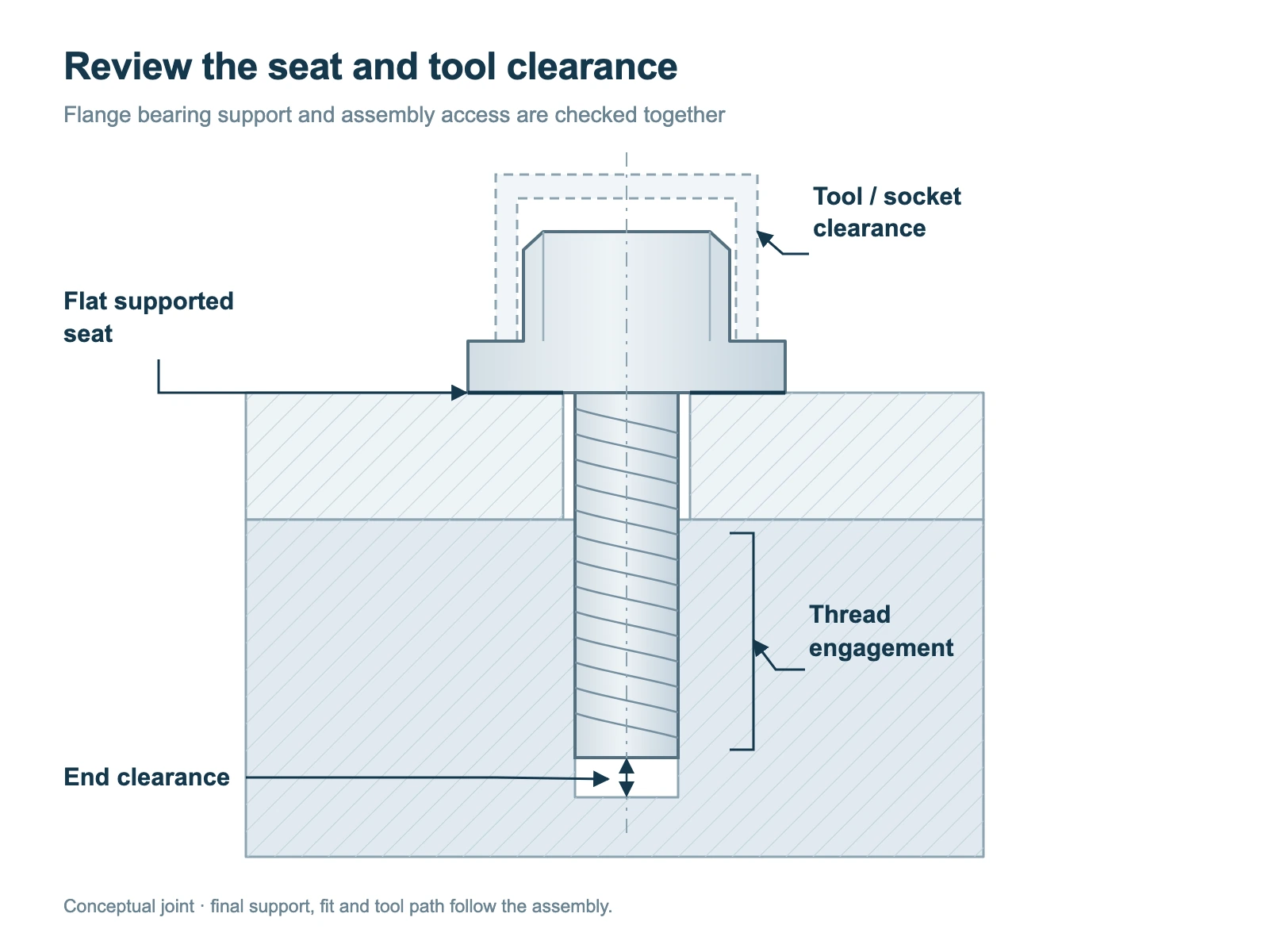
A wider flange still needs a supported seat
An enlarged flange can overlap a hole or slot while still having too little support beneath it. Thin, curved or locally uneven panels can also change the contact area. We review flange dimensions with the mating geometry so that the intended bearing surface is part of the design, rather than an assumption based on head diameter.
The head fits, but the tool does not
A fastener can clear the surrounding parts and still leave too little room for its installation tool. Comparing the external hex, rounded button and broad truss profiles helps define the head envelope; drive size and access must then be checked with the actual assembly path.
The finished part fits differently from the uncoated sample
A coating can change thread fit, drive-recess clearance and the condition of the bearing face. Material, finish and final inspection requirements are reviewed together, so the sample approval relates to the specified finished configuration.
Match the Head Profile to the Assembly
Flange-head geometry can be considered for equipment covers, brackets and housings where contact area and installation space need to be managed together. The application sets the requirements; the head shape alone does not establish load capacity or suitability.
| Assembly situation | Profiles to compare | What determines the fit |
|---|---|---|
| Equipment covers and finished panels | Button or truss flange profiles | Head envelope, supported contact area, hole coverage and the permitted effect on the visible surface. |
| Brackets and mechanical housings | External hex flange profiles | Socket or wrench access, seating geometry, engagement and the specified connection load. |
| Restricted space around the fastener head | Hex, button and truss profiles compared against the available envelope | Both the installed head dimensions and the access path for the actual assembly tool. |
For a tapped-hole or nut connection, thread engagement and the mating thread remain part of the specification. Load-bearing assemblies follow the approved joint design and validation requirements.
Custom Geometry with a Manufacturing Plan

Custom external hex flange-head geometry.
Head and flange geometry reviewed together
Flange diameter, thickness, head height and drive geometry affect both assembly fit and manufacturability. Shi Shi Tong reviews these features together with the material, thread and critical dimensions, so a head-profile change is assessed as part of the complete screw design.
A route selected for the actual part
Cold heading and precision machining provide different routes for flange-head designs. The route is selected around the material, geometry, quantity and acceptance requirements, with tooling development and sample validation where needed. Secondary machining is used where the part and process call for it.
Manufacturing and Inspection in Shenzhen
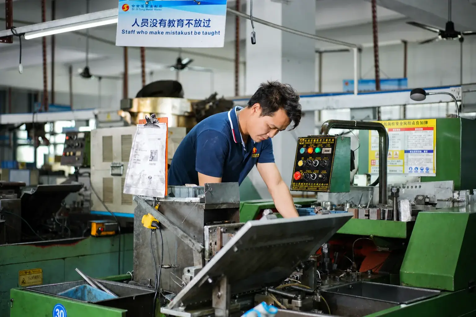
Shi Shi Tong has been manufacturing screws since 1998. Drawing review, process planning and sample validation connect the specified geometry with the production and inspection requirements for the part.
Inspection can include dimensional measurement, optical profile checks and thread gauging, according to the approved specification. Hardness, torque and surface-related testing are defined where the project requires them, with test conditions and acceptance criteria agreed for the relevant part.
Features that matter on a flange-head screw
- Head and flange dimensions, drive geometry and seating features.
- Thread designation, engagement-related dimensions and finished fit.
- Material, finish and the inspection records specified for the project.

Optical profile inspection of screw geometry.
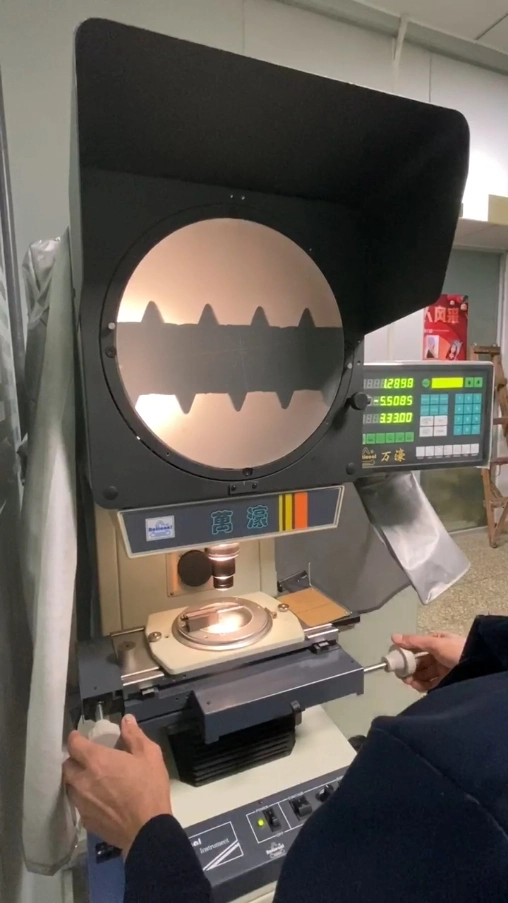
Thread gauge inspection of a metal fastener.
Flange Head Screw Selection Guide
Use these checks to evaluate the bearing surface, service conditions and purchasing specification alongside the three head profiles.
Can a flange head screw replace a separate washer?
It can in some joints, when the integral flange provides the bearing coverage and contact conditions required by the design. Combining the head and flange also removes a separate washer from that configuration.
A separate washer may still be needed for a specified hardness, larger bearing diameter, surface interface or another defined function. An integral flange is also different from a screw assembled with separate flat and spring washers. The hex, button and truss profiles here describe the integral head geometry; whether a washer can be removed is a connection-design decision.
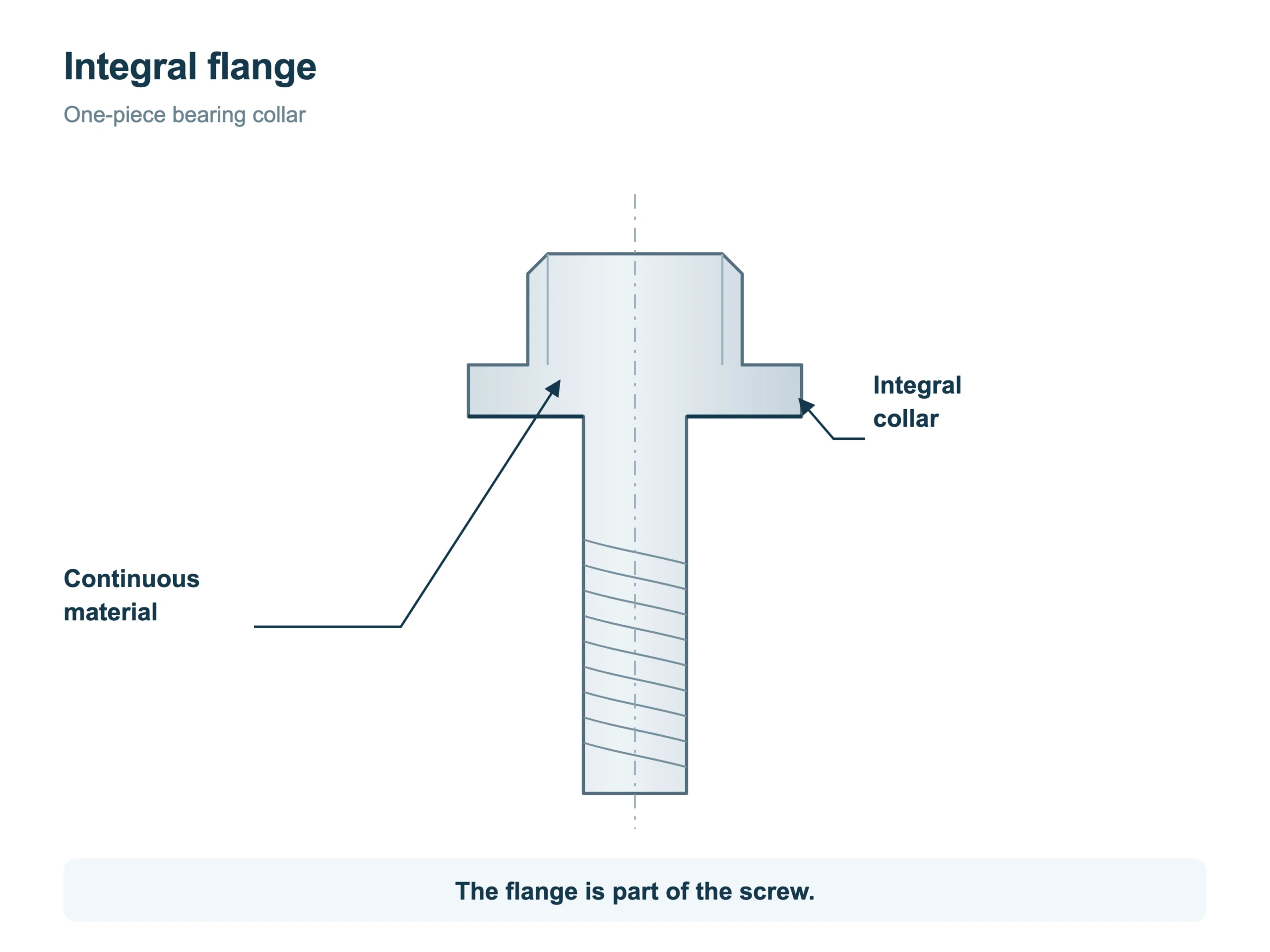 Integral flange
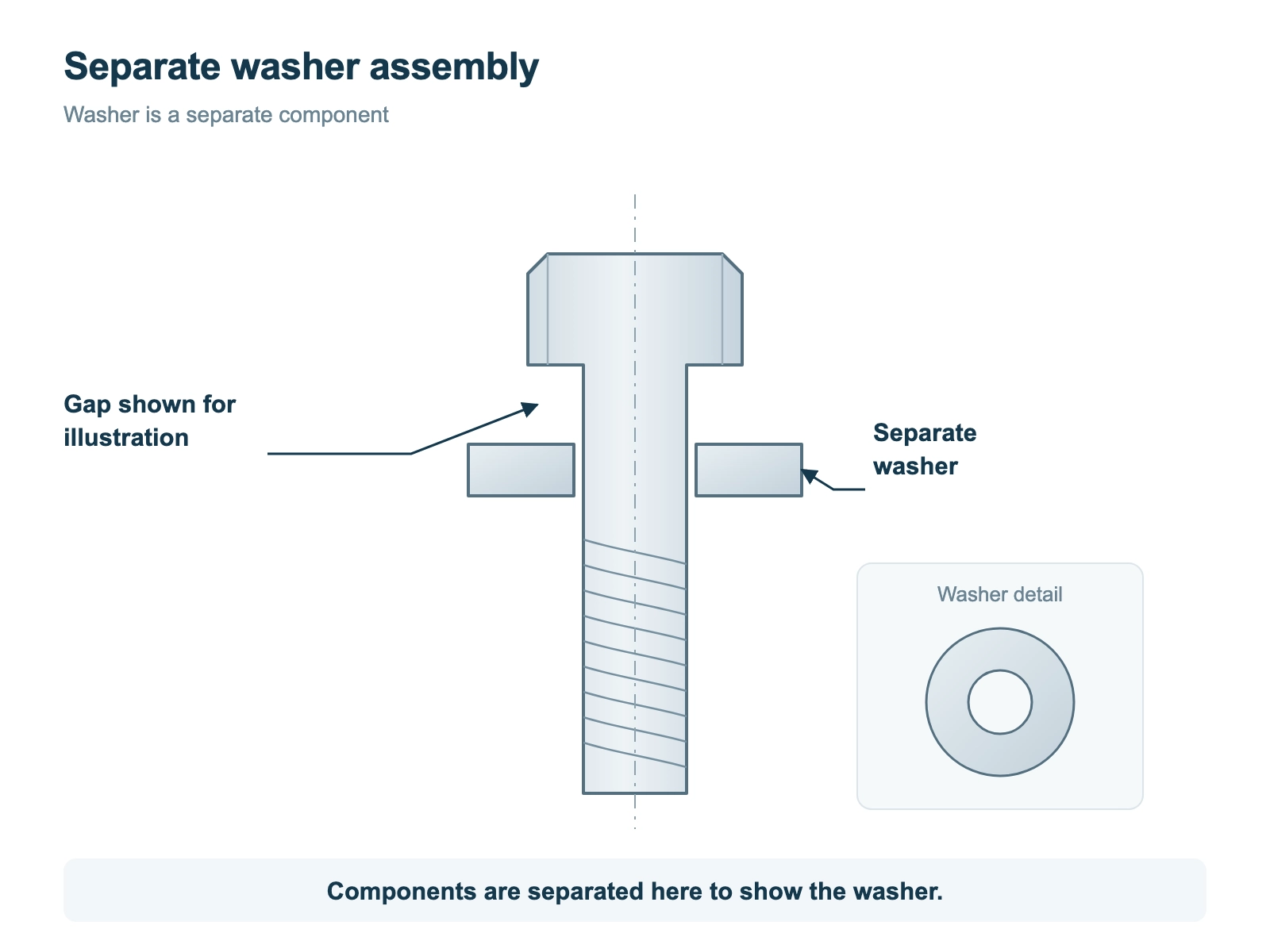 Separate washer assembly
Should I choose a smooth or serrated flange?
A smooth bearing face is a starting point when continuous contact or control of surface marking is important. It still creates contact pressure and friction during tightening; a smooth face does not guarantee a mark-free panel.
Serrations create a different contact with the mating surface and may mark or penetrate a coating. Their effect depends on the mating material, finish, joint load and assembly conditions. The serrated hex-flange configuration can be reviewed against those requirements, but serrations alone do not establish vibration resistance or remove the need for joint validation. A torque value from a different bearing-face or coating condition should not be transferred without checking the connection.

How should I specify flange screws for outdoor use?
Start with the exposure conditions: moisture, chlorides, cleaning chemicals, temperature and contact with other metals. Select the exact material grade and finish for that environment, then consider the head geometry and the condition of the surface beneath the flange.
Stainless steel grades such as 304 and 316L have different corrosion characteristics, but neither is suitable for every environment. Carbon or alloy steel requires an appropriate protective system where corrosion is a concern. These material directions are reviewed with the specific flange-head design rather than treated as interchangeable options for every geometry.
Black appearance is not a corrosion specification. State the finish, test method and acceptance criteria where required. Salt-spray results relate to the tested part and conditions; they do not directly establish an outdoor service life.
How can I compare custom flange screw quotations?
Compare quotations against the same drawing revision and finished-part requirements. A unit price based on a different flange profile, material condition or inspection scope is not a like-for-like comparison.
- The selected head profile, flange dimensions, thread and tolerances.
- The exact material grade, required properties and surface finish.
- Order quantity and the basis for repeat production.
- Tooling and sample charges, where applicable.
- Inspection, documentation, packaging and delivery terms included in the quotation.
Shi Shi Tong reviews the drawing and project requirements before defining the manufacturing route and quotation. Sample arrangements, order quantity and lead time are established for the individual project.
Discuss Your Flange Head Screw Drawing
Share a drawing or describe the head profile, flange dimensions, thread, material, finish and estimated quantity. We will review the configuration, manufacturing route and sample or inspection requirements for your project.
For an existing assembly, include the mating-hole details and available head and tool space.